
Linear motor controller

Active Publication Date: 2005-08-04
FISHER & PAYKEL APPLIANCES LTD
View PDF28 Cites 31 Cited by
  • Summary
  • Abstract
  • Description
  • Claims
  • Application Information

AI Technical Summary

Benefits of technology

[0005] It is an object of the present invention to provide a linear motor controller which goes some way to achieving the above mentioned desiderata.

Problems solved by technology

The application of excess motor power for the conditions of the fluid being compressed may result in the piston colliding with the cylinder head in which it is located.

Method used


Image

  • Linear motor controller
  • Linear motor controller
  • Linear motor controller

Examples


Embodiment Construction

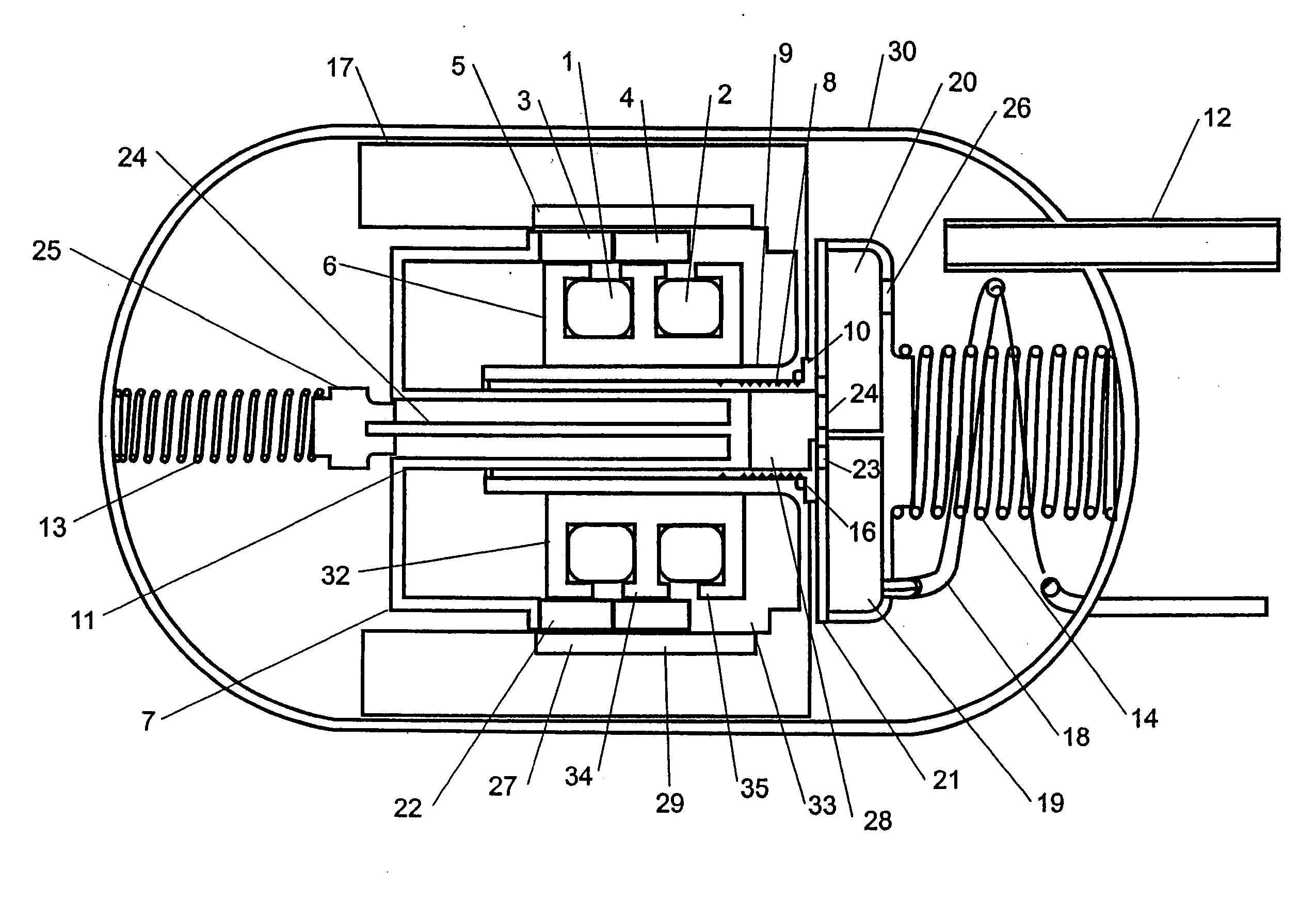
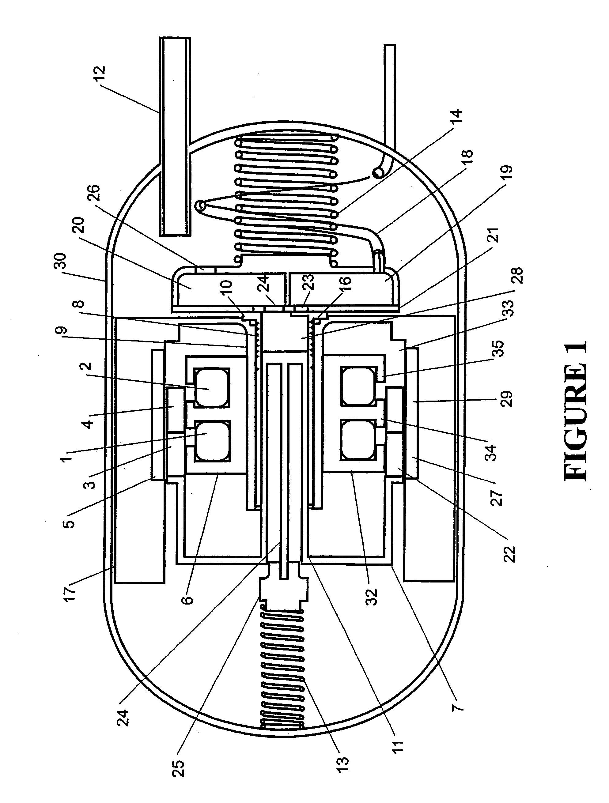
[0034] The present invention provides a method for controlling a free piston reciprocating compressor powered by a linear motor of the type shown in FIG. 1. Firstly it has a reduced size compared to the conventional linear motor of the type described in U.S. Pat. No. 4,602,174 and thus reduces the cost. This change keeps the efficiency high at low to medium power output at the expense of slightly reduced efficiency at high power output. This is an acceptable compromise for a compressor in a household refrigerator which runs at low to medium power output most of the time and at high power output less than 20% of the time (this occurs during periods of frequent loading and unloading of the refrigerator contents or on very hot days). Secondly it uses a control strategy which allows optimally efficient operation, while negating the need for external sensors, which also reduces size and cost.

[0035] While in the following description the present invention is described in relation to a cy...


PUM


Abstract

A sensorless method of detecting piston collisions in a reciprocating free piston linear compressor driven by an electronically commutated linear motor having at least one excitation winding is provided. A free piston gas compressor is also provided.

Description

[0001] This application is a continuation application of U.S. patent application Ser. No. 10 / 898,808, filed on Jul. 26, 2004 (pending), which is a divisional application of U.S. patent application Ser. No. 10 / 293,874, filed on Nov. 13, 2002, which issued as U.S. Pat. No. 6,812,597 on Nov. 2, 2004.FIELD OF INVENTION [0002] This invention relates to a controller for a linear motor used for driving a compressor and in particular but not solely a refrigerator compressor. SUMMARY OF THE PRIOR ART [0003] Linear compressor motors operate on a moving coil or moving magnet basis and when connected to a piston, as in a compressor, require close control on stroke amplitude since unlike more conventional compressors employing a crank shaft stroke amplitude is not fixed. The application of excess motor power for the conditions of the fluid being compressed may result in the piston colliding with the cylinder head in which it is located. [0004] In International Patent Publication no. WO01 / 79671 t...

Claims


Application Information

Patent Timeline
IPC IPC(8): F04B35/04F04B49/06
CPCF04B2201/0209F04B35/045F04B49/06H02P7/02H02K33/16F04B2203/04F05B2210/12Y10S388/923Y10S388/935Y10S417/00
Inventor MCGILL, IANTAIN, ZHUANG
Owner FISHER & PAYKEL APPLIANCES LTD
Learn More