
Resonant arrangement for a linear compressor

a linear compressor and resonant technology, applied in the direction of positive displacement liquid engine, pump components, pumping, etc., can solve the problems of inability to properly fix, high price of flat springs, and relatively difficult to obtain flexible rods, etc., to achieve easy and reliable

Inactive Publication Date: 2005-07-28
EMPRESA BRASILEIRA DE COMPRESSORES SA (EMBRACO)
View PDF13 Cites 60 Cited by
  • Summary
  • Abstract
  • Description
  • Claims
  • Application Information

AI Technical Summary

Benefits of technology

"The patent describes a resonant arrangement for a linear compressor that includes a non-resonant assembly, a resonant assembly, and an actuating means. The non-resonant assembly is made up of a motor and a cylinder, while the resonant assembly consists of a piston that moves back and forth inside the cylinder. The actuating means connects the piston to the motor. The arrangement also includes at least one spring means that is connected to both the non-resonant assembly and the resonant assembly. The spring means has a tubular body that is folded in a way that allows it to elastically deform when the piston moves. This arrangement helps to improve the performance of the linear compressor by resonating the piston movement and reducing the noise generated during the compression process."

Problems solved by technology

This construction presents some disadvantages, such as the need to have a flexible rod to neutralize the forces resulting from the errors occurred during production and assembly of the parts.
This flexible rod is also a relatively difficult component to be obtained, since it must be produced with special materials.
Furthermore, such flat springs are very expensive, as they require very sophisticated cutting and finishing processes.
This construction also presents disadvantages, such as requiring a compressor with larger dimensions, as a function of the need to use a pair of helical springs, which cannot be properly affixed to be submitted to traction forces.
Moreover, the helical springs have the characteristic of generating eccentric and shearing forces on the surfaces on which they are seated, provoking forces on the bearings of the piston of the compressor, generating noise and wear and reducing the life of the compressor.

Method used


Image

  • Resonant arrangement for a linear compressor
  • Resonant arrangement for a linear compressor
  • Resonant arrangement for a linear compressor

Examples


Embodiment Construction

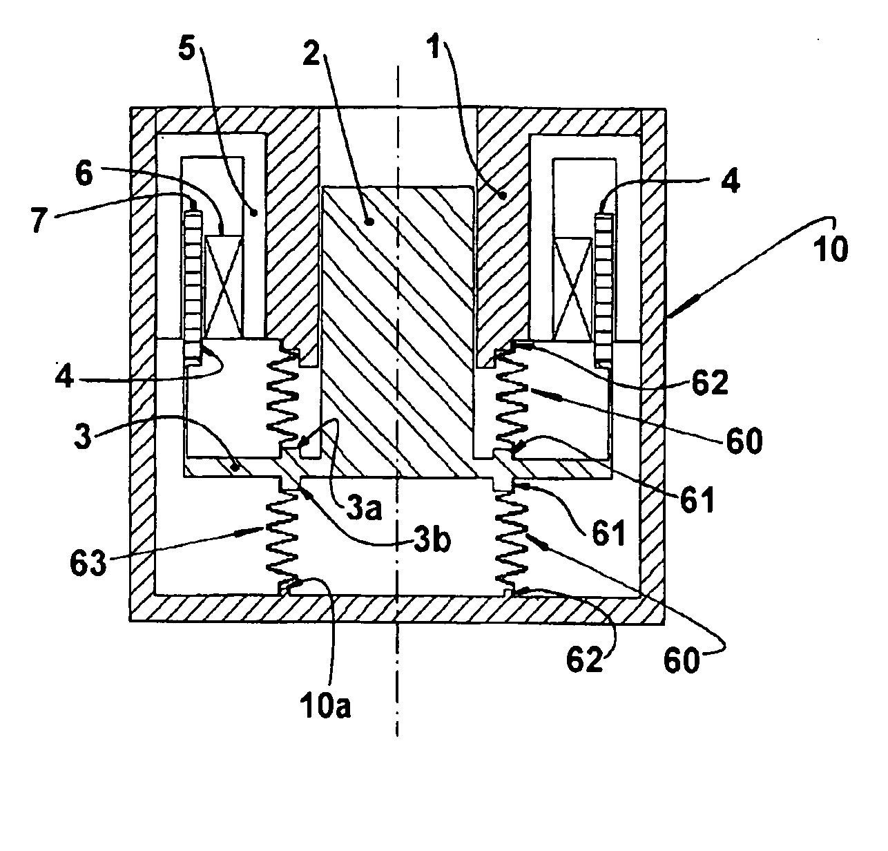
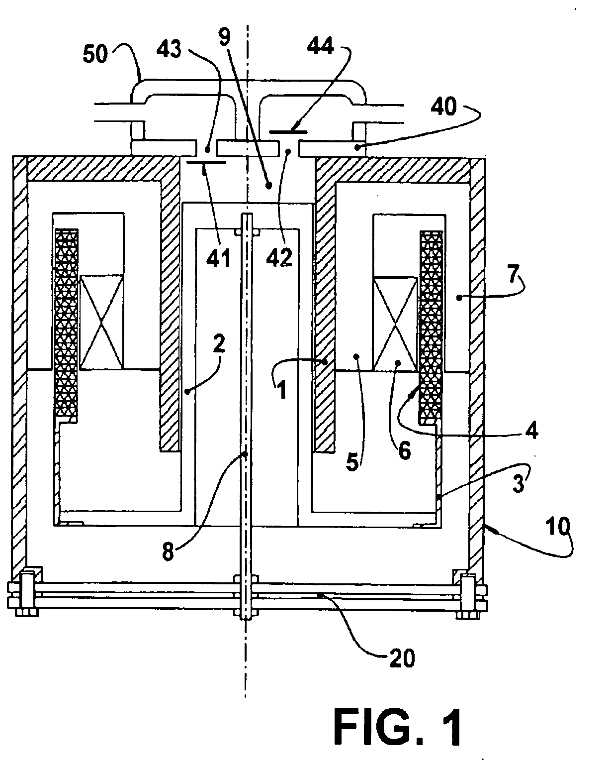
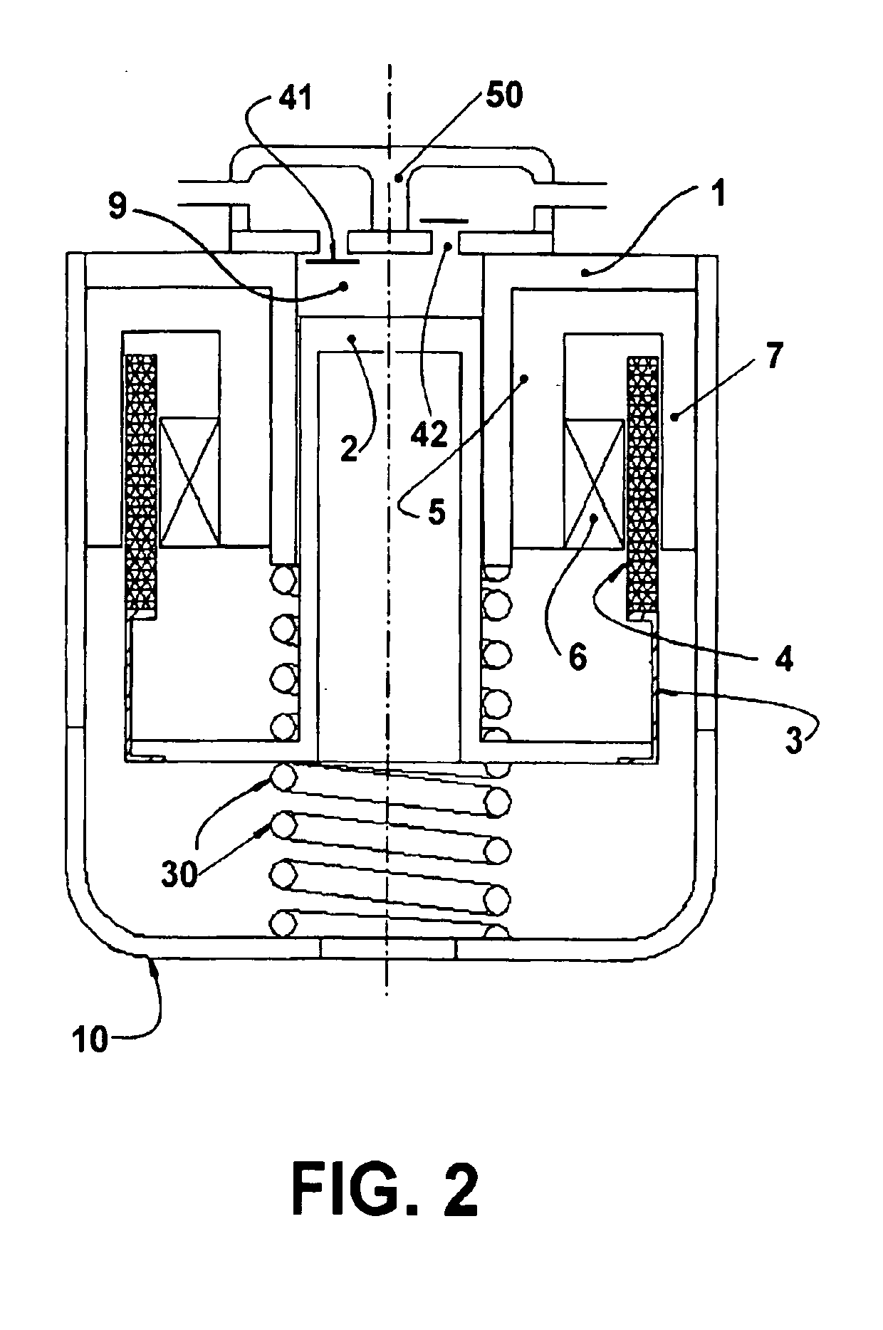
[0020] The present invention will be described in relation to a reciprocating compressor driven by a linear motor of the type used in refrigeration systems and comprising a motor-compressor assembly, including a non-resonant assembly formed by a linear motor and a cylinder 1, and a resonant assembly formed by a piston 2 reciprocating inside the cylinder 1, and an actuating means 3, external to the cylinder 1 and carrying a magnet 4 that is axially impelled upon energization of the linear motor, said actuating means 3 operatively coupling the piston 2 to the linear motor.

[0021] According to the prior art construction illustrated in FIGS. 1 and 2, the components mentioned above are mounted inside a hermetic shell 10.

[0022] As illustrated in the enclosed figures, the linear motor is mounted around the cylinder 1 and the piston 2 and comprises a stack of internal laminations 5 with a coil 6 inserted therein, and a stack of external laminations 7.

[0023] In the construction illustrated...


PUM


Abstract

A resonant arrangement for a linear compressor, comprising a non-resonant assembly formed by a motor and a cylinder (1); a resonant assembly formed by a piston (2) reciprocating inside the cylinder (1); an actuating means (3) operatively coupling the piston (2) to the motor, and at least one spring means presenting an elongated tubular body (50) which is coaxial to the axis of the piston (2) and is operatively coupled to the actuating means (3) and to the non-resonant assembly, said tubular body (50) having at least part of the extension therof folded in circumferential sectors (53), each circumferential sector (53) being elastically deformed in the axial direction upon displacement of the piston (2).

Description

FIELD OF THE INVENTION [0001] The present invention refers, in general, to a constructive arrangement for a resonant compressor of the type driven by a linear motor to be applied in refrigeration systems and which presents a piston reciprocating inside a cylinder. BACKGROUND OF THE INVENTION [0002] In a reciprocating compressor driven by a linear motor, the gas suction and gas compression operations are performed by the reciprocating axial movements of the piston inside a cylinder, which is closed by a cylinder head and mounted within a hermetic shell, in the cylinder head being positioned the suction and discharge valves that control the admission and discharge of the gas in relation to the cylinder. The piston is driven by an actuating means that supports magnetic components driven by a linear motor affixed to the shell of the compressor. [0003] In some constructions, the piston is mounted against a resonant spring means in the form of an assembly of flat springs, affixed to the h...

Claims


Application Information

Patent Timeline
Patent Type & Authority Applications(United States)
IPC IPC(8): F04B35/04
CPCF04B35/045
Inventor BERWANGER, EGIDIOPUFF, RINALDO
Owner EMPRESA BRASILEIRA DE COMPRESSORES SA (EMBRACO)
Learn More