
Integrated induction battery charge apparatus

a charge apparatus and induction battery technology, applied in battery overcharge protection, safety/protection circuits, transportation and packaging, etc., can solve the problems of charging methods that remain troublesome and cannot be solved, and the charging environment restrictions

Inactive Publication Date: 2005-07-28
INVENTEC CORP
View PDF4 Cites 91 Cited by
  • Summary
  • Abstract
  • Description
  • Claims
  • Application Information

AI Technical Summary

Benefits of technology

[0007] The second induction module is at the battery end to enable the induction charge apparatus to charge induction batteries of different specifications. Hence users need to carry only one type of charger. This resolves the problem of preparing dedicated chargers for different specifications of batteries. This is more convenient.

Problems solved by technology

However, charging methods still are a troublesome issue remained to be resolved.
Such an approach has charging environment restrictions (such as submerged).
This is very inconvenient.

Method used


Image

  • Integrated induction battery charge apparatus
  • Integrated induction battery charge apparatus
  • Integrated induction battery charge apparatus

Examples


Embodiment Construction

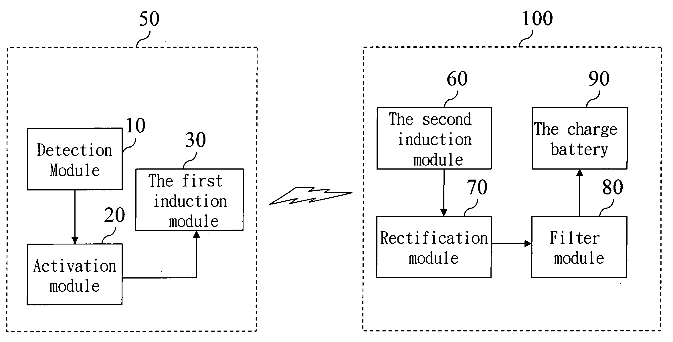
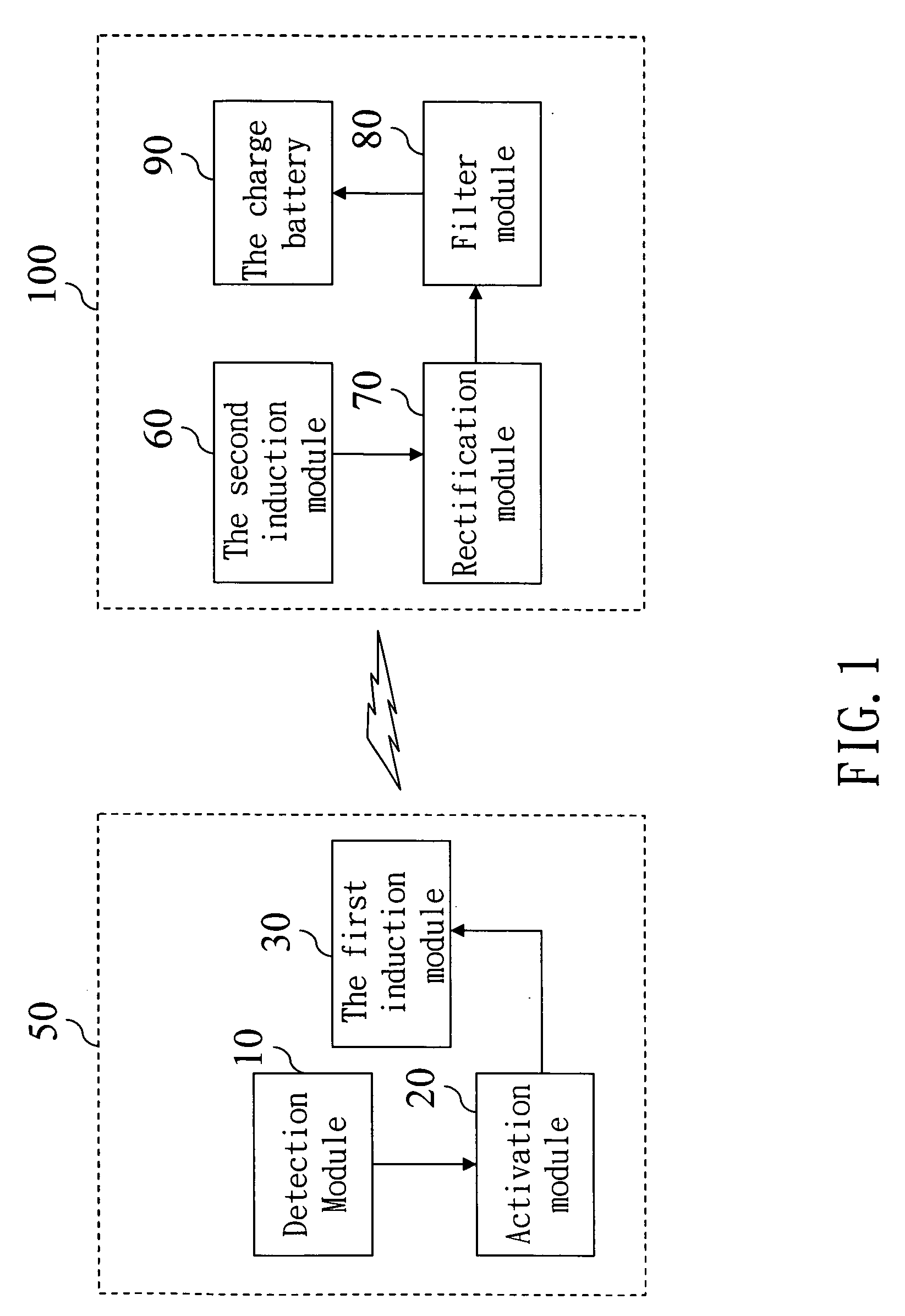
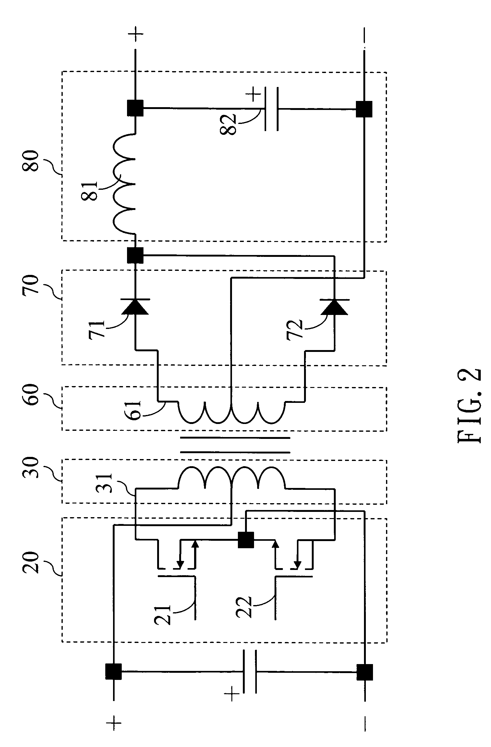
[0012] Refer to FIG. 1 for a functional block diagram of the invention. The integrated induction battery charge apparatus according to the invention aims at employing electromagnetic induction principles, to charge chargeable batteries. It includes a detection module 10, an activation module 20, a first induction module 30, a second induction module 60, a rectification module 70, a filter module 80 and a charge battery 90.

[0013] The detection module 10 is located at a charging end 50, to send a detection signal to a battery end 100 and receive a response signal, to indicate the presence of the charge battery 90, and generate an activation signal to start the charging process. The module uses the detection approach to control the electromagnetic induction charge process and to prevent the charging end 50 from continuously sending out induction electromagnetic waves when the charging process stops. Further, it uses the detection approach to avoid causing interference to the signal tr...


PUM


Abstract

An integrated induction battery charge apparatus transforms electric energy and magnetic energy according to electromagnetic induction principle to charge an induction charge battery. It integrates the conventional charge batteries to become an induction charge battery so that users may carry only one charge apparatus to charge the induction batteries of different specifications, thereby improve use convenience.

Description

FIELD OF THE INVENTION [0001] The present invention relates to an induction battery charge apparatus and particularly to an integrated induction battery charge apparatus. BACKGROUND OF THE INVENTION [0002] These days, portable electronic devices are very popular, due to their use convenience. However, charging methods still are a troublesome issue remained to be resolved. [0003] Conventional charging methods generally adopt a conductive charging approach. It is accomplished by connecting metal contacts, to direct electric energy into the battery for charging. Such an approach has charging environment restrictions (such as submerged). It also has to couple with dedicated chargers to match various battery specifications (such as 18.5 V, 15 V, 10 V, etc.), and many interface specifications (such as 5-pin legs, 6-pin legs, 7-pin legs, etc.). [0004] When charging is required, a dedicated charging dock or dedicated DC power supply has to be provided. If the batteries of multiple number of...

Claims


Application Information

Patent Timeline
Patent Type & Authority Applications(United States)
IPC IPC(8): H02J7/00H02J7/02
CPCH02J7/025H02J7/00302H02J50/10H02J50/60
Inventor YU, WIN-CHEEWU, CHIEN-LI
Owner INVENTEC CORP
Learn More