Method and apparatus for applying a polycrystalline film to a substrate

Inactive Publication Date: 2005-07-28
REAL TIME RADIOGRAPHY
View PDF3 Cites 10 Cited by
  • Summary
  • Abstract
  • Description
  • Claims
  • Application Information

AI Technical Summary

Benefits of technology

[0014] It is an object of the present invention to provide a film deposition system, including a deposition chamber and ancillary elements, which allows for substantially optimal directional growth of films on large area substrates and where large voids are not found on the surface of the film.
[0015] It is a further object of the system to provide a film deposition system for physical vapor deposition that will allow for a more efficient use of the precursor source material by reducing parasitic deposition on areas of the system other than the large-area substrate. This reduction in parasitic deposition allows for better maintenance of the equilibrium vapor pressure in the deposition chamber and therefore produces better films.
[0016] It is yet another object of the present invention to provide a method for physical vapor deposition wherein large area substrates may be coated with negligible parasitic losses and wherein the film produced has optimal orientation and high density.
[0021] This method allows for the formation of a highly oriented film on the substrate with the total mass of film-forming material lost through parasitic losses being less than the film mass deposited on the large area substrate.

Problems solved by technology

The system described by Iwanczyk is based on equipment designed for single crystal formation employing glass ampoules and is limited to small substrates.
These prior art systems, however, do not optimize the working characteristics of the deposited films.
These parasitic losses of film-forming material lower vapor pressure in the coating chamber adversely affecting the quality of the deposited film.
Finally, prior art systems have difficulty in depositing quality films on large area substrates.

Method used


Image

  • Method and apparatus for applying a polycrystalline film to a substrate
  • Method and apparatus for applying a polycrystalline film to a substrate
  • Method and apparatus for applying a polycrystalline film to a substrate

Examples


Embodiment Construction

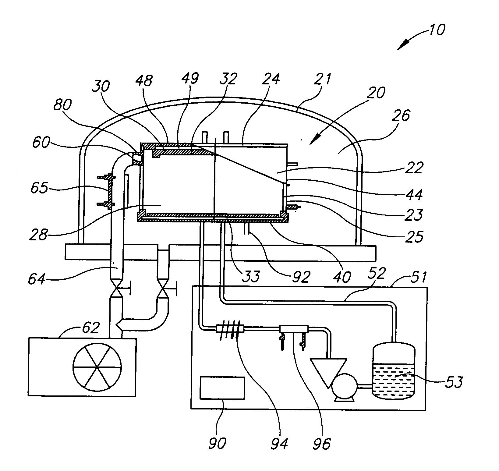
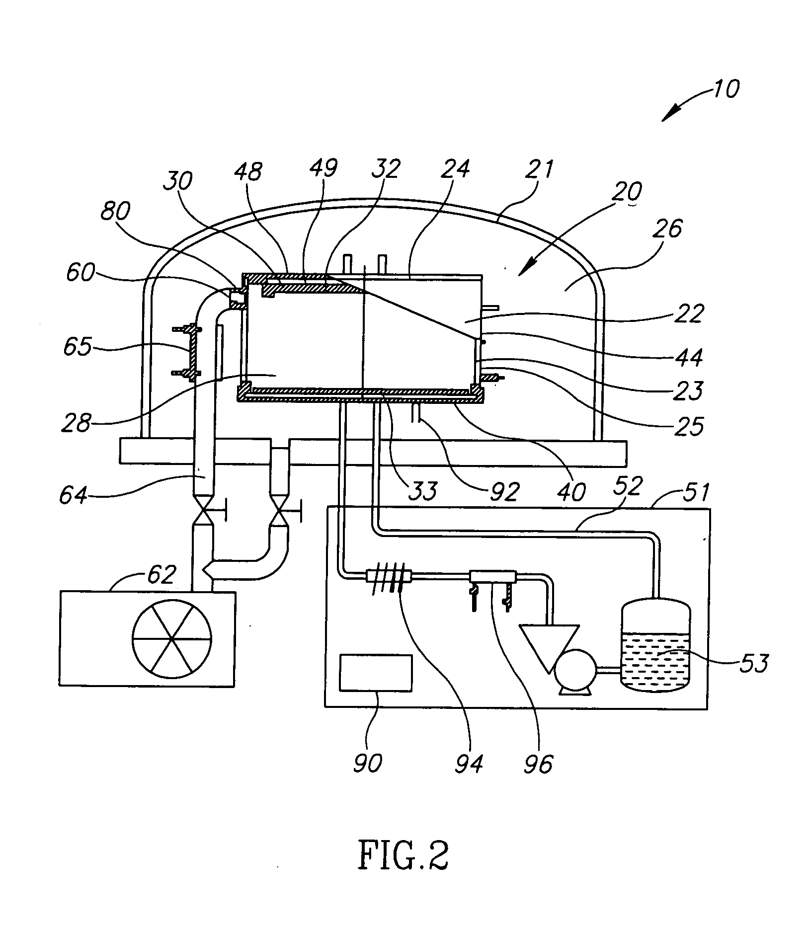
[0032] A non-equilibrium vapor pressure during film deposition in physical vapor deposition systems affects the quality of deposited films. This is especially true for large area substrates. Among other factors, parasitic losses lead to decreases in vapor pressure and non-equilibrium conditions in such systems.

[0033] While the effect of parasitic losses in coating small area substrates may be controllable without undue effort, this is not the case for large area substrates. The inventors have realized that a rigorous control of the deposition system by creating at least three distinct highly controlled temperature regimes therein allows for the production of high quality films. A method has been developed, and a film deposition system designed, that is based on rigorous temperature control. Such control allows for the maintenance of uniform temperatures throughout the substrate producing high quality films, particularly high quality wide band gap semiconductor films on large area s...


PUM

PropertyMeasurementUnit
Areaaaaaaaaaaa
Digital informationaaaaaaaaaa
Temperatureaaaaaaaaaa

Abstract

A film deposition system for depositing a polycrystalline film on a large area substrate. The system includes a chamber formed of a set of walls, the set of walls defining at least three temperature zones within the chamber. Each of the walls is thermally insulated from the other walls forming the chamber. The system further includes a vacuum source, a set of heat sources, and a plurality of temperature detectors for detecting the temperature of the walls in the set of walls. Temperature control modules monitor and control the temperature in each of the temperature zones. The temperature control modules maintain predetermined temperatures in the walls so that the total mass of film-forming material lost through parasitic losses is less than the film mass deposited on the large area substrate. A method for depositing a polycrystalline film is also described.

Description

[0001] This application claims the benefit of U.S. Provisional Application No. 60 / 538,511, to Grin et al, filed Jan. 26, 2004, entitled “Method and Apparatus for Applying a Polycrystalline Film to a Substrate,” which is incorporated herein by reference.FIELD OF THE INVENTION [0002] The present invention relates to an apparatus, which is a film deposition system, and a method for applying a polycrystalline film to a substrate for use in high energy radiation detectors and imagers. DEFINITIONS [0003] Substrate—either a unitary, single piece substrate or an array of small substrates being coated simultaneously. [0004] Parasitic losses—material lost as a result of deposition of film-forming material anywhere in the film deposition system other than on the substrate intended to be coated. [0005] Parasitic deposition—deposition of film-forming material anywhere in the film deposition system other than on the substrate intended to be coated. [0006] Apparatus—used interchangeably herein wit...

Claims


Application Information

Patent Timeline
IPC IPC(8): B05C11/00C23C14/06C23C14/22C23C14/54C23C16/00
CPCC23C14/0694C23C14/541C23C14/22
Inventor GRIN, ASHERBREEN, BARRY N.GILBOA, HAIMMELEKHOV, LEONID
Owner REAL TIME RADIOGRAPHY
Why Eureka
Try Eureka