
Mounting element for a bowden cable

a technology of mounting elements and bowden cables, which is applied in the direction of linear movement shafts, flexible shafts, shafts, etc., can solve the problems of not providing a solution for the disassembly of mounting elements, and achieve the effect of cost-effective production and less effort in assembly

Inactive Publication Date: 2005-07-28
FICO TRIAD
View PDF13 Cites 7 Cited by
  • Summary
  • Abstract
  • Description
  • Claims
  • Application Information

AI Technical Summary

Benefits of technology

[0011] Therewith, the mounting element according to the invention comprises the advantage to consist substantially only of three components, wherein its assembly is done by a simple inserting of the latch into the latching housing, which allows a very cost-efficient assembly. Due to this simple assembly motion, also an automatic assembly of the latching element is easily possible.
[0012] Further, it is advantageous that the spring-biased latch does latch with the support structure particularly save and enduring, so that a particularly reliable latching of the mounting element is achieved.
[0013] A further advantage of the inserting, respectively nesting, of the latch through the latching housing is the possibility to provide actuation elements at the side, which is opposed to the latching elements. With these actuation elements, the latch can be pulled back against a spring force, to release the latching with the support structure. So, the mounting element can be dismounted from the support structure without destroying it and also without tools.
[0015] So, the latch preferably comprises an actuation element for the manual de-latching of the latch. The actuation element is preferably provided as a pulling knob and is arranged at the side of the latch, which is opposite to the latching elements. The latch can so easily be grasped by hand or with a nippers at the pulling knob and be drawn against the spring force. So, an easy destruction-free dismounting of the mounting element from the support structure is possible.
[0016] In a preferred embodiment, the mounting element consists only of three single components. Therewith, it can cost-efficiently be produced and be assembled with less effort.
[0020] Preferably, the locking element comprises a resilient arm, a locking pin, an actuation face, and a first and a second locking pawl. Particularly preferred, the locking pin engages into a locking cavity and therefore prevents a displacement of the latch.

Problems solved by technology

So, it is often the problem to mount the bowden cable at one end at a fixed support structure, so that the cable sheath can rest upon the stationary support structure, while the pulling cable of the bowden cable actuates a desired element.
However, these solutions do not provide a solution for the disassembly of the mounting element from the support structure.

Method used


Image

  • Mounting element for a bowden cable
  • Mounting element for a bowden cable
  • Mounting element for a bowden cable

Examples


Embodiment Construction

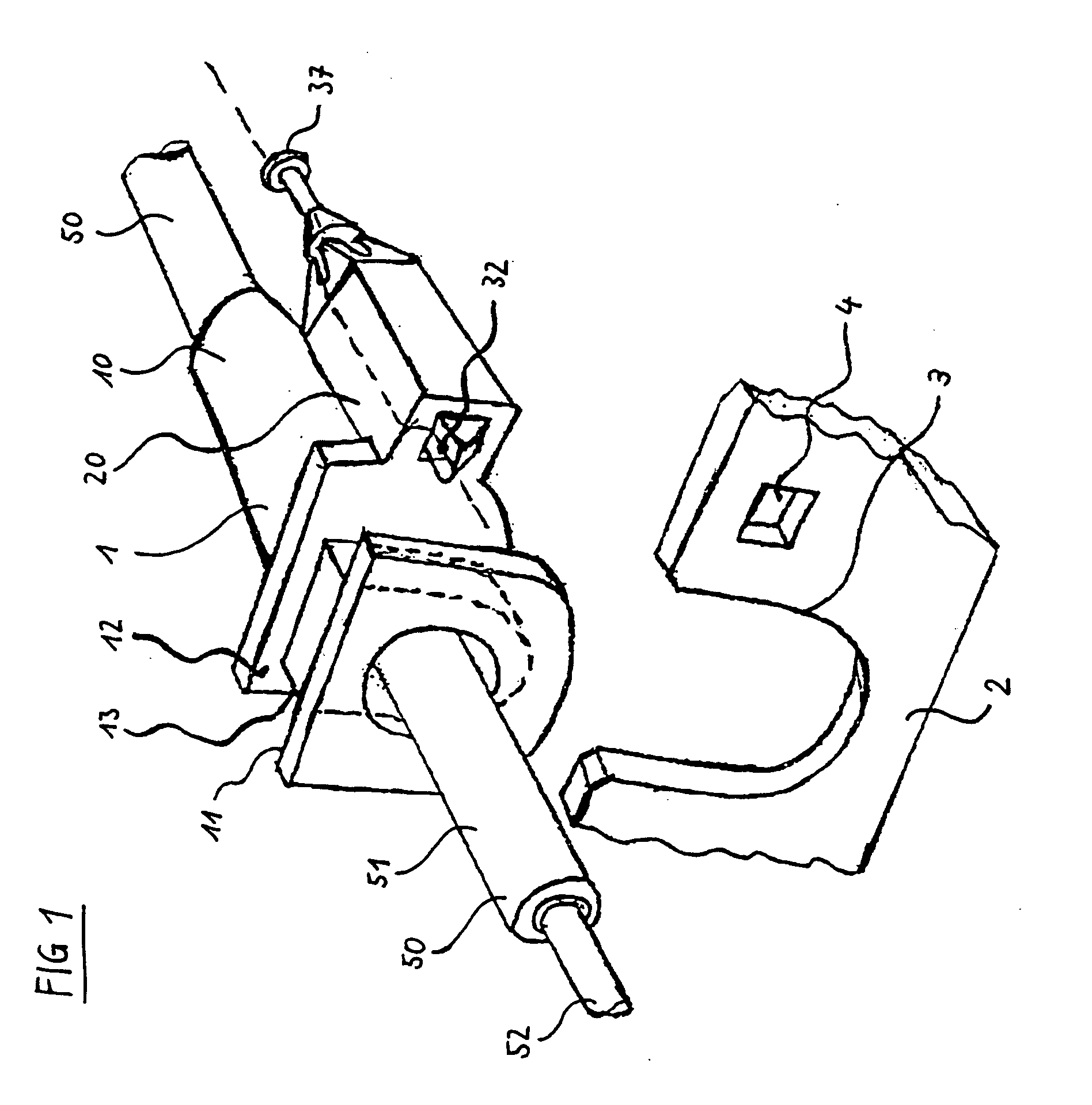
[0029] A first preferred embodiment of the present invention is shown in FIG. 1. FIG. 1 shows a mounting element 1, a bowden cable 50, as well as a support structure 2 to which the bowden cable 50 should be connected using the mounting element 1.

[0030] The mounting element 1 comprises a mounting body 10 through which the bowden cable 50 extends. The bowden cable 50 can loosely extend through the mounting body 10, i.e. to be displaceably arranged as whole within the mounting element 1, or the bowden cable 50 is connected to the mounting body 10 so that a cable sheath 51 of the bowden cable 50 is not displaceable with respect to the mounting body 10. In this case, the cable sheath 51 rests against the mounting body 10 of the mounting element 1, wherein forces can be applied to the support structure 2 after the mounting. The bowden cable 50 further comprises a pulling cable 52 which is displaceably arranged within the cable sheath 51. Via the pulling cable 52 and the cable sheath 51 o...


PUM


Abstract

The present invention relates to a mounting element 1 for a bowden cable 50, particularly for the automotive engineering, comprising a mounting body 10 with a at least partially circumferential mounting slot 13, wherein the mounting slot 13 can be brought into engagement with an essentially U-shaped seat 3 within a support structure by sliding; a latching element 20, for latching the mounting body 10 with the support structure 2, wherein the latching element 20 comprises a displaceable latch 30, a spring 25 and a latching housing 21, which is open at opposed sides; wherein the latch 30 comprises a snap element 35, so that the latch 30 is latchable with the latching housing 21 by insertion of the latch 30 into the latching housing 21.

Description

[0001] This application claims priority on EP 03015673.1 filed Jul. 18, 2003, which is incorporated herein by reference. 1. TECHNICAL AREA [0002] The present invention relates to a mounting element for the mounting of a bowden cable to a support structure, particularly for the use in the automotive area. 2. PRIOR ART [0003] The prior art provides different solutions for mounting elements of bowden cables. In general bowden cables are used for the transmission of pulling or pushing forces over longer distances and in different directions. In automotive engineering, bowden cables are for example used as brake cables, clutch cables, accelerator cables or also for the heating adjustment or the like. So, it is often the problem to mount the bowden cable at one end at a fixed support structure, so that the cable sheath can rest upon the stationary support structure, while the pulling cable of the bowden cable actuates a desired element. For this purpose and for a simplified assembly, moun...

Claims


Application Information

Patent Timeline
IPC IPC(8): F16C1/26
CPCF16C1/105Y10T74/20462F16C2326/01F16C1/262F16C2326/20
Inventor DONA-CONTERO, JUAN-MANUEL
Owner FICO TRIAD
Learn More