
Radio-controlled timepiece and electronic device, control method for a radio-controlled timepiece, and reception control program for a radio-controlled timepiece

a radio-controlled timepiece and electronic device technology, applied in radio-controlled timepieces, instruments, horology, etc., can solve problems such as interference with normal signal reception, signal cannot be received, difficult reception, etc., to achieve power conservation and improve reception reliability.

Active Publication Date: 2005-07-21
SEIKO EPSON CORP
View PDF10 Cites 36 Cited by
  • Summary
  • Abstract
  • Description
  • Claims
  • Application Information

AI Technical Summary

Benefits of technology

[0018] External signals can thus be received more accurately and reception reliability can be improved because the control means has a reception operation control means that controls reception by the reception unit based on the radio-controlled timepiece location detection signal from the location detection means so that, for example, the external signal is received only when a location detection signal indicating that the radio-controlled timepiece is located where reception is possible is output from the location detection means. Furthermore, because whether the timepiece is located where reception is possible is detected by the location detection means and external signals are received based on the resulting detection signal, wasteful reception attempts are prevented and power consumption by the radio-controlled timepiece is reduced.
[0068] This aspect of the invention affords the same effects as a radio-controlled timepiece described above according to the present invention, promotes power conservation by the radio-controlled timepiece, and improves reception reliability.

Problems solved by technology

In addition, Japanese Unexamined Patent Application 2000-221284 teaches a radio-controlled timepiece that receives the standard time signal when the timepiece is not moving because reception is difficult when the timepiece is moving.
The effects of electromagnetic noise produced when the generating means is producing power can interfere with normal signal reception when the generating means is producing power.
However, while this radio-controlled timepiece can receive the standard time signal under certain circumstances while the timepiece is moving, the signal cannot be received if the timepiece moves to a location where the standard time signal cannot be received, for example.
Furthermore, because the standard time signal is received and the time is adjusted when a change from a stationary to a moving state is detected, the power conservation mode is cancelled and the standard time signal is unconditionally received when the radio-controlled timepiece is picked up to be worn.
However, reception may or may not succeed at this time depending upon the location where reception is attempted and the orientation of the bar antenna of the timepiece, and the correct time may not be displayed.
If the signal cannot be correctly received at this time, the power supply of the radio-controlled timepiece is needlessly drained, and power conservation cannot be improved for the radio-controlled timepiece.
However, this type of radio-controlled timepiece consumes more power than the previous radio-controlled timepiece because the standard time signal is received even when the power conservation mode is active, and power consumption by the timepiece is not particularly reduced.
Furthermore, if the radio-controlled timepiece is left in a location where the standard time signal cannot be received, this timepiece will automatically repeatedly attempt to receive the standard time signal at the scheduled reception time even while the power conservation mode is active, and power conservation by the radio-controlled timepiece cannot be improved.
Yet further, if the radio-controlled timepiece that receives the standard time signal when the timepiece is not moving is in an automobile and the automobile is not moving but the standard time signal cannot be correctly received because the vehicle is stopped in the midst of tall buildings, for example, standard time signal reception may succeed or fail even though reception is controlled based on detection of movement, and reliable reception therefore may not be assured.
Improving power conservation in such radio-controlled timepieces may therefore not be possible in such timepieces because of such wasted attempts to receive the standard time signal.
However, if the timepiece is located where standard time signal reception is poor, such as inside an office building, the timepiece may not be able to receive the time signal correctly.
Such reception control cannot assure sufficient reception reliability and results in needless reception operations, and improved power conservation thus also cannot be provided with this type of radio-controlled timepiece.
However, reception is not possible in some situations, such as when the radio-controlled timepiece is in a location where the standard time signal cannot reach, and these radio-controlled timepieces therefore lack sufficiently reliable signal reception.
As a result, these radio-controlled timepieces consume much power when reception is attempted where the standard time signal cannot be received.
Furthermore, because receiving the standard time signal consumes much more power than does simply driving the timekeeping mechanism, power consumption due to needless reception attempts is a particularly significant drawback.

Method used


Image

  • Radio-controlled timepiece and electronic device, control method for a radio-controlled timepiece, and reception control program for a radio-controlled timepiece
  • Radio-controlled timepiece and electronic device, control method for a radio-controlled timepiece, and reception control program for a radio-controlled timepiece
  • Radio-controlled timepiece and electronic device, control method for a radio-controlled timepiece, and reception control program for a radio-controlled timepiece

Examples


embodiment 1

[0091] A first preferred embodiment of the present invention is described below with reference to the accompanying figures.

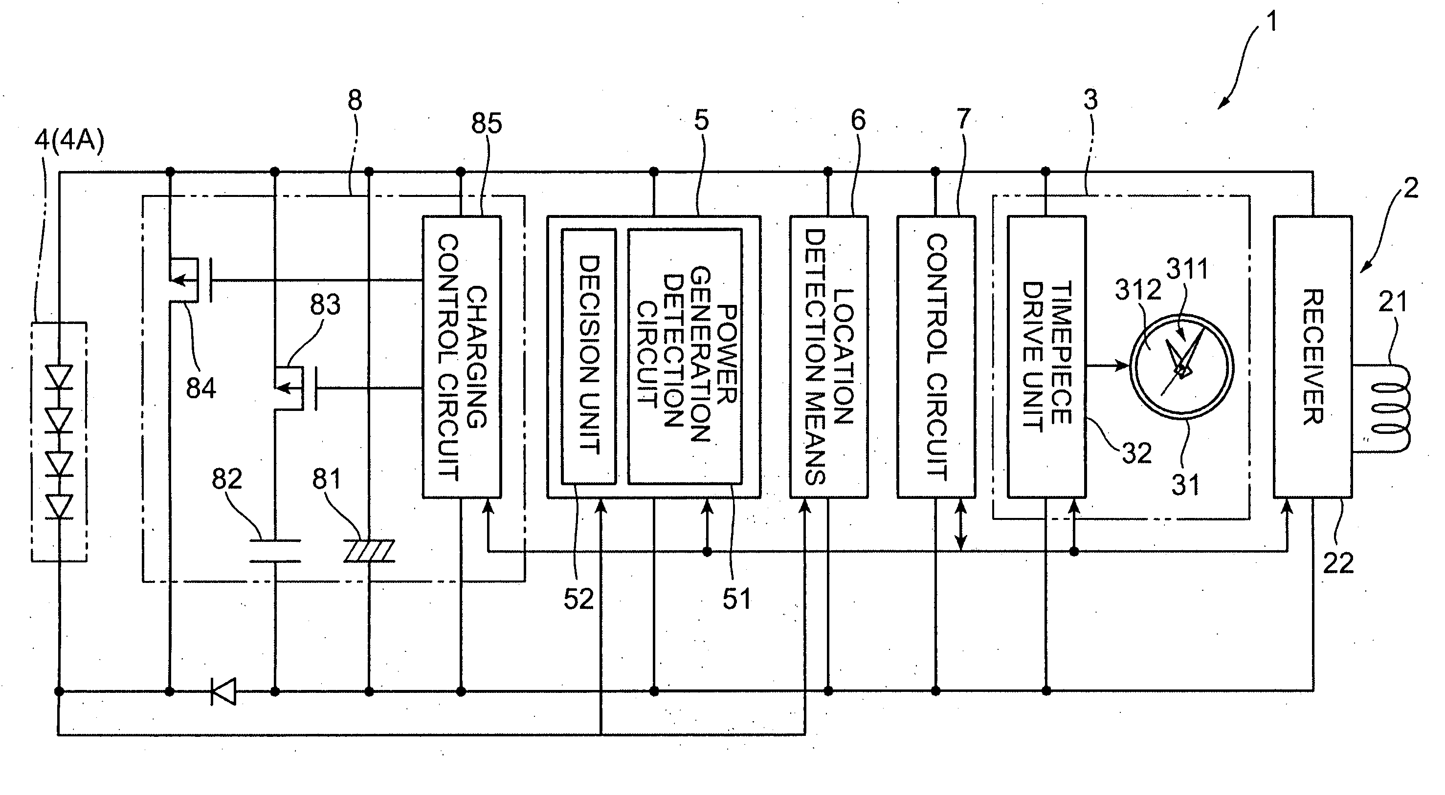
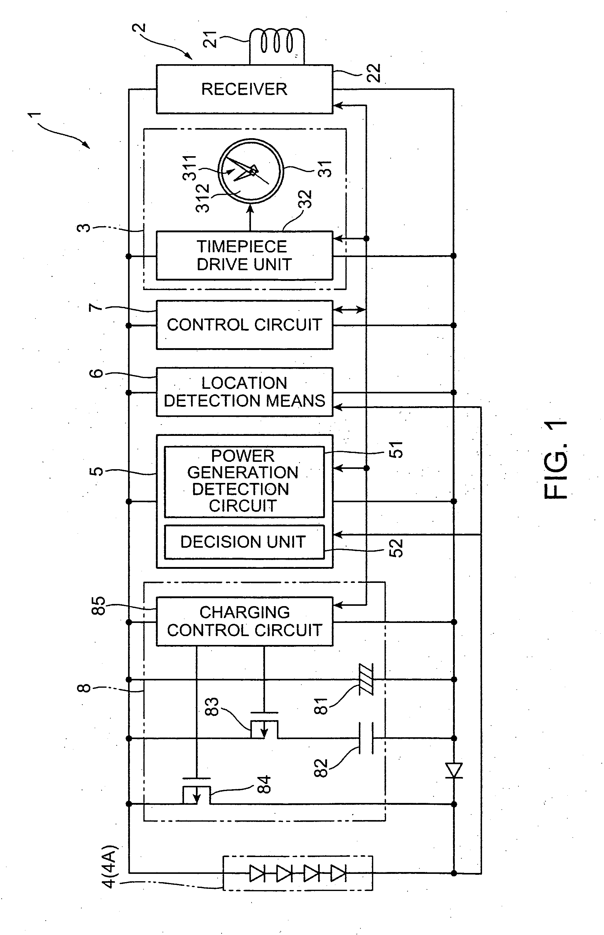
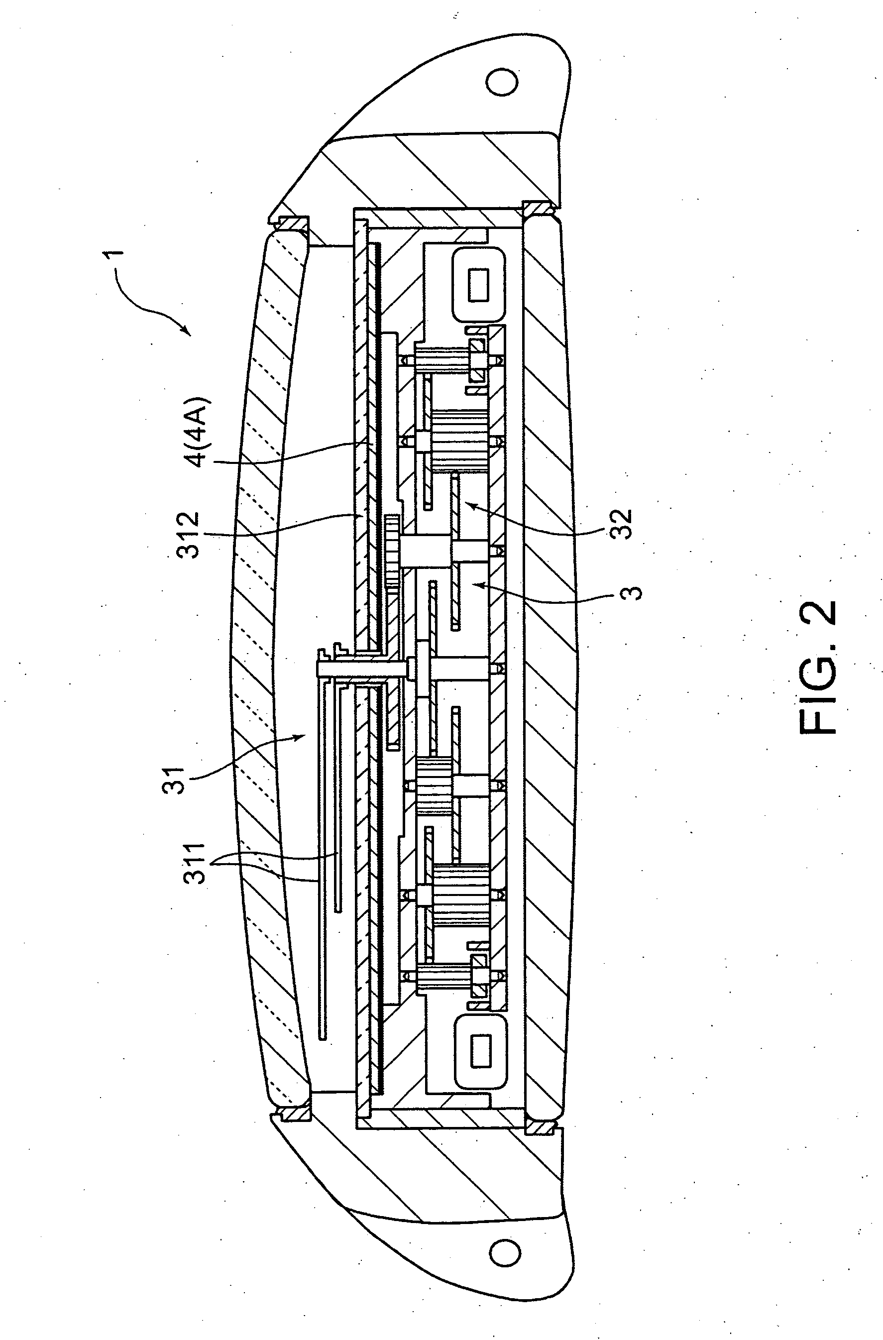
[0092]FIG. 1 is a function block diagram of a radio-controlled timepiece 1 according to a first embodiment of the present invention. FIG. 2 is a side section view of the radio-controlled timepiece 1. A radio-controlled timepiece 1 according to this embodiment of the invention is a radio-controlled timepiece that adjusts the displayed time based on a standard time signal (external signal) carrying superimposed time information broadcast from an external source, and more specifically is a wristwatch that can be worn by a user.

[0093] As shown in FIG. 1 and FIG. 2, this radio-controlled timepiece 1 has a receiver 2 for receiving a standard time signal, a time display means 3 for displaying time based on a reference signal, a generating means 4 for producing power by converting external energy to electrical energy, a motion detection means 5 for detecting if the ra...

second embodiment

[0165] A second embodiment of the present invention is described next below. This second embodiment differs from the foregoing embodiment in that a different type of power generating means is used, and the external signal reception operation of the control means differs.

[0166]FIG. 9 is a function block diagram of a radio-controlled timepiece 1 according to this second embodiment of the invention. In addition to a photoelectric generating means 4 (4A) as used in the first embodiment, the generating means 4 in this second embodiment also has a mechanical generating means 4 (4B) for converting external mechanical energy to electrical energy as shown in FIG. 9.

[0167]FIG. 10 is an oblique view of this mechanical generating means 4 (4B). As shown in FIG. 10, this mechanical generating means 4 (4B) has a rotary pendulum 41, a power transfer mechanism 42, and a generator 43.

[0168] The rotary pendulum 41 is connected to a rotating shaft 41A by an intervening ball bearing not shown. The ce...

third embodiment

[0203] A third embodiment of the present invention is described next below. This third embodiment of the invention differs from the radio-controlled timepiece 1 of the second embodiment by additionally having a power conservation function.

[0204] The power conservation function in this embodiment of the invention monitors the supply voltage of the power supply 8, and if the supply voltage is less than or equal to a specified threshold value functions to reduce power consumption by, for example, stopping movement of the hands 311 until the supply voltage recovers or use resumes. Note that the control circuit 7 is driven when the power conservation function is active so that the supply voltage can be monitored, for example.

[0205] The control circuit 7 has a power conservation circuit not shown that provides the power conservation function. The power conservation circuit monitors the supply voltage of the power supply 8, and outputs a power conservation signal to the control circuit 7...


PUM


Abstract

A motion detection means 5 has a power generation detection circuit 51 for detecting the output voltage of a generating means 4, and a decision unit 52 for determining if the radio-controlled timepiece 1 is moving based on the output voltage from the power generation detection circuit 51. If when a standard time signal is to be received by means of a receiver 2 the not moving detection signal indicating that the radio-controlled timepiece 1 is not moving is output from the motion detection means 5, the reception operation is executed and the time displayed on the time display means 3 is adjusted. By receiving the standard time signal when the radio-controlled timepiece 1 is not moving, accurate time information can be received and the reliability of standard time signal reception can be improved because the reception success rate is also improved.

Description

BACKGROUND OF THE INVENTION [0001] 1. Field of Technology [0002] The present invention relates to a radio-controlled timepiece, an electronic device having a radio-controlled timepiece, a method of controlling a radio-controlled timepiece, and a reception control program for a radio-controlled timepiece. [0003] 2. Description of Related Art [0004] Radio-controlled timepieces, which receive a standard time signal carrying time information, include timepieces that automatically unconditionally receive the standard time signal according to a predetermined schedule, and timepieces that detect movement of the timepiece and receive the standard time signal accordingly. [0005] More specifically, Japanese Patent 3313215, for example, teaches a radio-controlled timepiece that detects if the timepiece is being worn or carried and receives the standard time signal while the radio-controlled timepiece is moving (see, for example, pages 5 to 7 and FIG. 1). This radio-controlled timepiece has a p...

Claims


Application Information

Patent Timeline
IPC IPC(8): G04G21/04G04R20/08
CPCG04R20/08G04G21/04G04R20/10
Inventor NAKAMURA, HIDENORI
Owner SEIKO EPSON CORP
Learn More