
Inkjet printhead with apertured sealing film

a sealing film and printhead technology, applied in printing, power drive mechanisms, inking apparatuses, etc., can solve the problems of inability to secure the ic to the surface, inability to provide sealing, and inability to ensure the ic, so as to avoid inadvertent ink leakage

Active Publication Date: 2005-07-21
SILVERBROOK RES PTY LTD +1
View PDF16 Cites 25 Cited by
  • Summary
  • Abstract
  • Description
  • Claims
  • Application Information

AI Technical Summary

Benefits of technology

[0020] The minimum thickness of the polymer sealing film will depend on a number of factors to be discussed in detail with reference to the preferred embodiments. However, the Applicant's analysis and testing has shown that a polymer sealing film thickness of 25 microns is adequate for the printhead IC's formed using lithographically masked etching and deposition techniques. Increasing the thickness to 50, 100 or even 200 microns will correspondingly increase the reliability of the seal provided.
[0032] wherein the ink storage compartment has a variable storage volume and a displaceable wall section biased to expand the variable storage volume to generate a negative pressure therein, such that ink does not inadvertently leak from the ink ejection nozzles.
[0047] during use, the ink storage compartment is maintained at a negative pressure to avoid inadvertent ink leakage from the nozzles;
[0054] wherein one of the opposed wall sections is displaceable and biased to expand the variable ink storage volume to create a negative pressure in the ink storage compartment for avoiding inadvertent ink leakage from the nozzles.
[0131] one of the opposed wall sections is displaceable and biased to expand the variable ink storage volume to create a negative pressure in the ink storage compartment for avoiding inadvertent ink leakage from the nozzles.

Problems solved by technology

However, if the surface of the support structure is uneven, the seal provided by the polymer film can be compromised.
The surface that the IC is secured to, is typically uneven because of more ink feed channels that deliver ink to the channels in the IC.
As the film seals across the open channels in the support, it can also bulge or sag into them.
The sagging may cause a gap between the walls separating each of the etched channels.
Obviously, this breaches the seal and allows ink to leak out of the printhead IC and or between etched channels.

Method used


Image

  • Inkjet printhead with apertured sealing film
  • Inkjet printhead with apertured sealing film
  • Inkjet printhead with apertured sealing film

Examples


Embodiment Construction

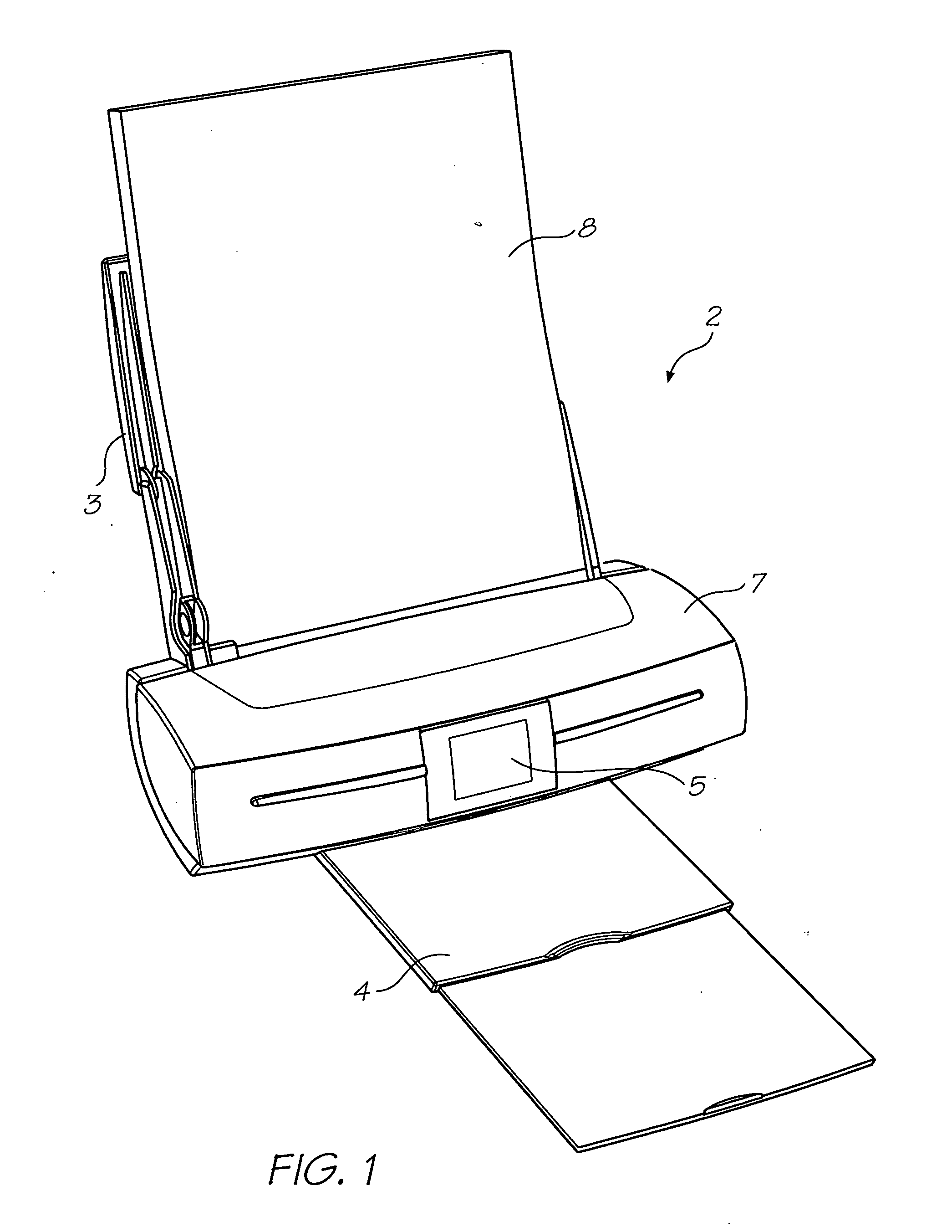
[0263]FIG. 1 shows a printer unit 2 embodying the present invention. Media supply tray 3 supports and supplies media 8 to be printed by the print engine (concealed within the printer casing). Printed sheets of media 8 are fed from the print engine to a media output tray 4 for collection. User interface 5 is an LCD touch screen and enables a user to control the operation of the printer unit 2.

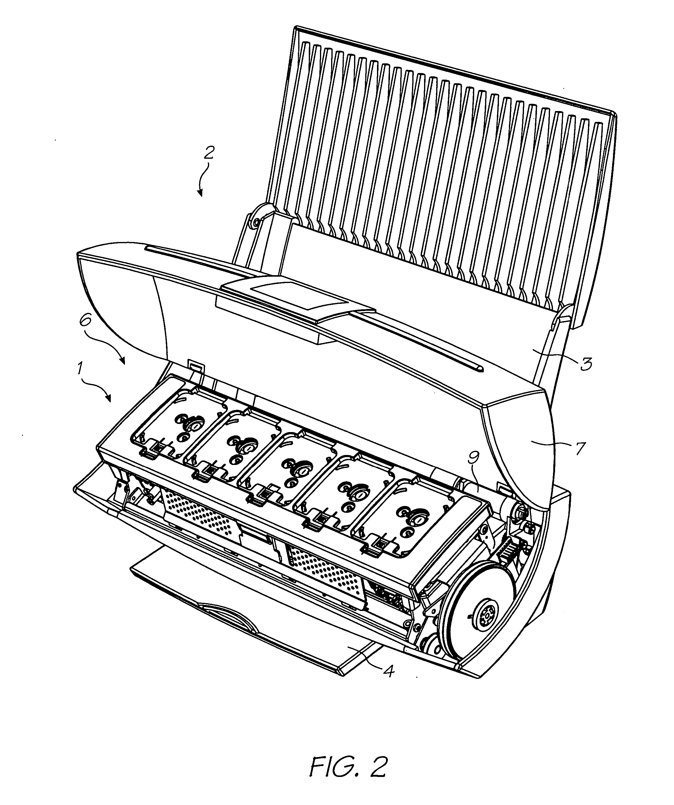
[0264]FIG. 2 shows the lid 7 of the printer unit 2 open to expose the print engine 1 positioned in the internal cavity 6. Picker mechanism 9 engages the media in the input tray 3 (not shown for clarity) and feeds individual streets to the print engine 1. The print engine 1 includes media transport means that takes the individual sheets and feeds them past a printhead assembly (described below) for printing and subsequent delivery to the media output tray 4 (shown retracted).

[0265]FIG. 3 schematically shows how the printer unit 2 is arranged to print documents received from an external source, ...


PUM


Abstract

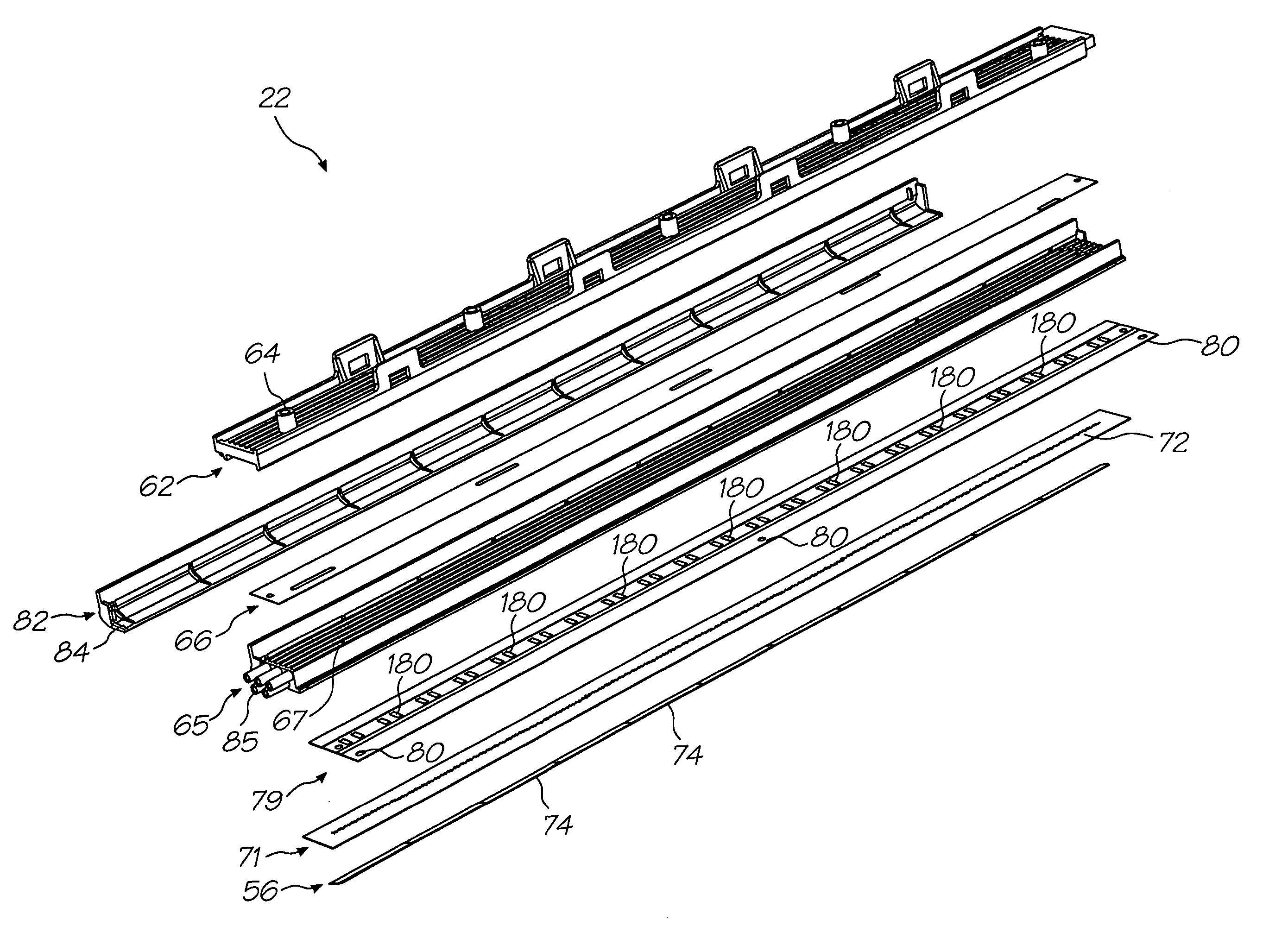
A printhead for an inkjet printer, the printhead comprising: a printhead integrated circuit having an array of ink ejection nozzles formed on a substrate; a plurality of ink feed conduits for establishing fluid communication with at least one ink storage compartment; and, a polymer sealing film between the ink feed conduits and the printhead integrated circuits, the polymer film having an array of apertures such that the ejection nozzles are in fluid communication with the ink feed conduits; wherein, the polymer sealing film is more than 25 microns thick.

Description

[0001] The present application is a Continuation-In-Part application of U.S. Ser. No. 10 / 760,254 filed on Jan. 21, 2004. In the interests of brevity, the disclosure of the parent application is incorporated in its entirety into the present specification by cross reference. [0002] CO-PENDING APPLICATIONS [0003] The following applications have been filed by the Applicant simultaneously with the present application: RRB001USRRB002USRRB003USRRB004USRRB005USRRB006USRRB007USRRB008USRRB009USRRB010USRRB011USRRB012USRRB013USRRB014USRRB015USRRB016USRRB017USRRB018USRRB019USRRB020USRRB021USRRB022USRRB023USRRB024USRRB025USRRB026USRRB027USRRB030USRRB031USRRB032USRRB033USRRC001USRRC002USRRC003USRRC004USRRC005USRRC006USRRC007USRRC008USRRC009USRRC010USRRC011USRRC012USRRC013USRRC014USRRC015USRRC016USRRC017USRRC018USRRC019USRRC020USMFA001USVPA001USVPA002USPNA001USWPA001USSHA001US[0004] The disclosures of these co-pending applications are incorporated herein by reference. The above applications have b...

Claims


Application Information

Patent Timeline
IPC IPC(8): B41J2/175B41J29/02
CPCB41J2/04541B41J2/17503B41J2/0458B41J2/04585B41J2/04591B41J2/14016B41J2/14427B41J2/155B41J2/1623B41J2/1628B41J2/1634B41J2/1637B41J2/1642B41J2/1648B41J2/16526B41J2/16535B41J2/16585B41J2/1707B41J2/1714B41J2/175B41J2/17506B41J2/17509B41J2/17513B41J2/1752B41J2/17536B41J2/17553B41J2/17556B41J2/17566B41J2/19B41J2/515B41J29/02B41J29/13B41J29/38B41J2002/14362B41J2002/14403B41J2002/14419B41J2002/14435B41J2002/14459B41J2002/14475B41J2002/14491B41J2002/1742B41J2002/17516B41J2202/19B41J2202/20B41J2202/21B41J2/135B41J2/04543B29C64/209B41J2/1742B41J25/34
Inventor SILVERBROOK, KIANAKAZAWA, AKIRAHIBBARD, CHRISTOPHERMACKEY, PAUL IANBERRY, NORMAN MICHEALJACKSON, GARRY RAYMOND
Owner SILVERBROOK RES PTY LTD
Learn More