Lighting apparatus formed by serially-Driven lighting units

a technology of lighting units and lighting devices, which is applied in the direction of instruments, light sources, optics, etc., can solve the problems of increasing production costs, large contributors to the cost and power consumption of lcd devices by backlight sources, and inability to achieve light-emission independently, so as to reduce the number of transformers and reduce the size of associated lcds , the effect of low cass

Inactive Publication Date: 2005-07-21
HON HAI PRECISION IND CO LTD
View PDF4 Cites 11 Cited by
  • Summary
  • Abstract
  • Description
  • Claims
  • Application Information

AI Technical Summary

Benefits of technology

[0013] In a second embodiment of the present invention, a current balance control circuit is disposed between the second end of the first lighting unit and the first end of the second lighting unit. The first end of the first port of the second transformer is connected to the current balance control circuit, and the second end of the first port of the second transformer is connected to ground. In this manner, each of the transformers can help implement feedback control.
[0014] Unlike in the prior art, the lighting apparatus of the present invention uses serial connection of the lighting units to reduce the number of transformers and still be able to apply the feedback control circuit or the current balance control circuits. Therefore, the amount of hardware elements of the lighting apparatus of the present invention is less than that of the prior art, and the size of an associated LCD is correspondingly reduced. The lighting apparatus of the present invention has advantages of compactness, low cass and high quality not provided by the prior art.

Problems solved by technology

The LCD cannot achieve light-emission independently; it generally has to rely on a backlight source.
Moreover, the backlight source is a large contributor to the cost and power consumption of the LCD device.
Backlight modules for this kind of display system are unduly large, and result in increased production costs.
If distortions in the current occur without any feedback, the brightness of the lamp 20 becomes unstable.
Therefore, in practice, the lighting apparatus 18 is not provided with a feedback control mechanism, and does not have the advantages of being able to make the lighting system stable and being able to accurately adjust the brightness of the lamps 20.
In the lighting apparatus 18, a feedback control mechanism cannot be provided, which makes it difficult to control the lamps 20.
However, conventional lighting apparatuses are unable to adequately meet this demand.

Method used


Image

  • Lighting apparatus formed by serially-Driven lighting units
  • Lighting apparatus formed by serially-Driven lighting units
  • Lighting apparatus formed by serially-Driven lighting units

Examples


first embodiment

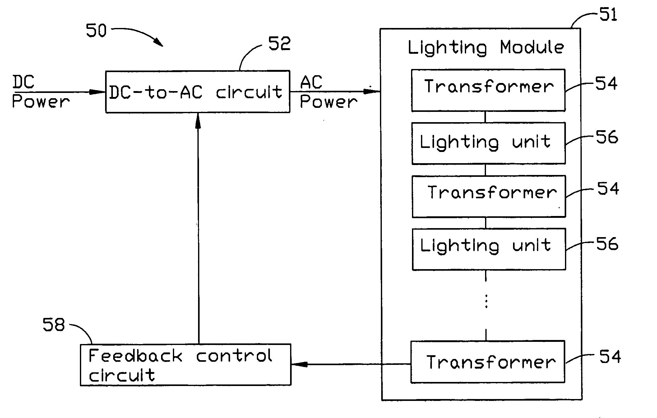
[0021]FIG. 1 illustrates a part of a lighting apparatus according to the present invention. Said part of the lighting apparatus comprises N lighting units 32, 34, . . . , 36, as well as N+1 transformers 35, 37, . . . , 39 (N being an integer greater than 1). Each of the transformers 35, 37, . . . , 39 has two ports: one input port and one output port. Each port has two ends to input or output voltage signals. When the input port receives low voltage AC power, the output port will transform the received low voltage AC power into high voltage AC power. The lighting units 32, 34, . . . , 36 of the present invention can be implemented by various lighting elements, such as discharge lamps. The N lighting units 32, 34, . . . , 36 are serially connected by the N+1 transformers 35, 37, . . . , 39 so that a positive high-voltage end and a negative high-voltage end of each lighting unit 32, 34, . . . , 36 are respectively connected to the transformers 35, 37, . . . , 39. Each two contiguous o...

second embodiment

[0025]FIG. 3 illustrates a lighting apparatus 60 according to the present invention. The lighting apparatus 60 comprises N lighting units 62, 64, . . . , 66, N−1 current balance control circuits 70, and N+1 transformers 65, 67, . . . , 69 (N being an integer greater than 1). All the transformers 65, 67, . . . , 69 and lighting units 62, 64, . . . , 66 are similar to the transformers 35, 37, . . . , 39 and lighting units 32, 34, . . . , 36 described above in relation to FIG. 1, except that the transformers 65, 67, . . . , 69 are allocated differently. The N lighting units 62, 64, . . . , 66 are serially connected by the N−1 current balance control circuits 70, so that each of the N−1 current balance control circuits 70 has a connection with two corresponding of the lighting units 62, 64, . . . , 66. In addition, each current balance control circuit 70 is connected to a corresponding one of the transformers 65, 67, . . . , 69. For example, the negative high-voltage end of the initial ...


PUM

PropertyMeasurementUnit
output currentaaaaaaaaaa
currentaaaaaaaaaa
AC poweraaaaaaaaaa

Abstract

A lighting apparatus includes a lighting module, a feedback control circuit, and a DC-to-AC circuit. The lighting module comprises a first lighting unit, a second lighting unit, a first transformer, a second transformer and a third transformer. A first end of a first port of the first transformer is connected to a first end of the first lighting unit, a first end of a first port of the second transformer is connected to a second end of the first lighting unit, a second end of the first port of the second transformer is connected to a first end of the second lighting unit, and a first end of a first port of the third transformer is connected to a second end of the second lighting unit. The lighting apparatus uses serial connection of the lighting units to reduce the number of transformers and still have the feedback control circuit.

Description

BACKGROUND OF THE INVENTION [0001] 1. Field of the Invention [0002] The present invention relates to a lighting apparatus such as that used in an LCD (Liquid Crystal Display), and more particularly to a lighting apparatus comprising serially-driven lighting units. [0003] 2. Prior Art of the Invention [0004] The improved quality and reduced costs of modern LCDs are making the LCD an increasingly popular choice in the field of display devices. LCDs are traditionally employed in notebook computers and other portable computer systems. LCD devices have made great progress in conjunction with the evolution of computer displays from the conventional VGA (Video Graphics Array) standard to the newer XGA (Extended Graphics Array) standard. Nowadays, LCD devices have a superior display quality to that of CRTs (Cathode Ray Tubes), and are poised to replace conventional CRT devices. [0005] The LCD cannot achieve light-emission independently; it generally has to rely on a backlight source. The ba...

Claims


Application Information

Patent Timeline
Patent Type & Authority Applications(United States)
IPC IPC(8): G02F1/13357G02F1/133H05B41/16H05B41/24H05B41/282
CPCH05B41/2822G02F1/133
Inventor LIN, SHIAN-NAN
Owner HON HAI PRECISION IND CO LTD
Why Eureka
Try Eureka