
Cleaning device and method

a cleaning device and cleaning technology, applied in the direction of spray nozzles, gaseous fuel burners, lighting and heating apparatus, etc., can solve the problems of inability to disinfect areas using conventional methods, degradation products, residual products, allergic reactions, etc., and achieve the effect of effectively exterminating certain kinds of pests

Inactive Publication Date: 2005-07-21
CTS RTECH
View PDF7 Cites 8 Cited by
  • Summary
  • Abstract
  • Description
  • Claims
  • Application Information

AI Technical Summary

Benefits of technology

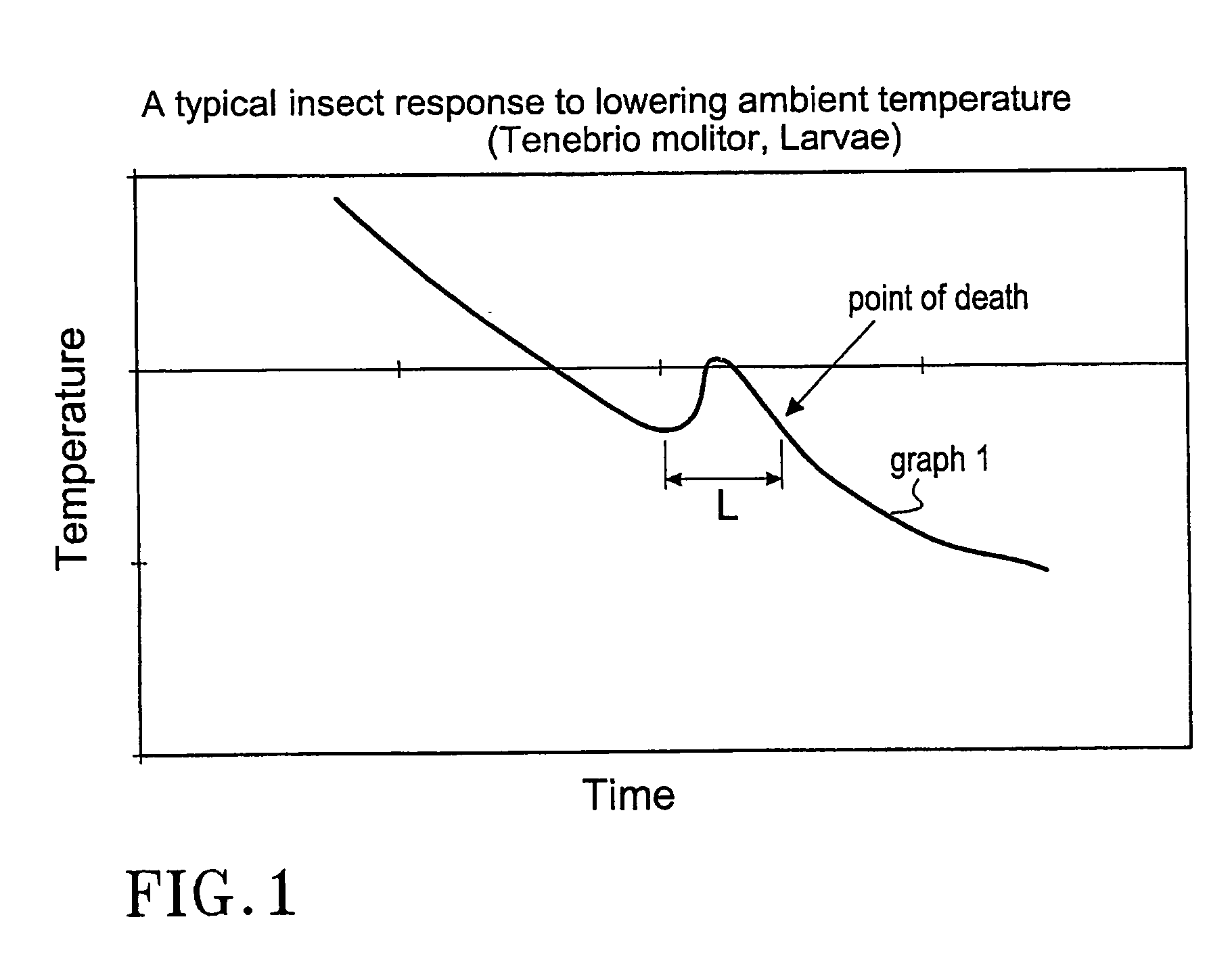
[0011] According to yet a further aspect of the invention, a device is provided for the extermination of pest such as for example insects and wood-louses, mites, etc., comprising the following steps: a) to first subject the pest for an atmosphere which entirely or partly is comprised of carbon dioxide during a predetermined time period, and then b) cool the pest to a temperature equally to or lower than a critical temperature Tkrit, wherein Tkrit is defined as the temperature wherein the pest is on the limit of freezing to death and / or respond with an increase of the body temperature. Further, according to another aspect of the invention a composition is provided for the extermination of pests comprising carbon dioxide in a solid state having a determined particle size adapted for the kind of pest that is to be exterminated and for the geometry said pest is located into. According to yet another aspect of the invention the use of carbon dioxide in a solid state is provided of a predetermined particle size for the manufacture of a composition arranged to effectively exterminate certain kinds of pests in a certain kind of determined geometry.

Problems solved by technology

Some of these areas are not possible to disinfect using conventional methods due to poison related risks or because they are out of reach for treatment.
Potential problems associated with conventional chemicals include degradation products, residual products, allergic reactions and a probable enrichment of harmful substances in the food chain.
This method is hazardous to the health since methyl bromide is used.
The problem using the known methods is that they do not describe an economical and environmental friendly approach seen from a production point of view, since they do not define the connection between how the cooling is performed and how carbon dioxide shall be delivered to obtain an optimal result.

Method used


Image

  • Cleaning device and method
  • Cleaning device and method
  • Cleaning device and method

Examples


example 1

Tests in a Double Bended Tube of Stainless Steel

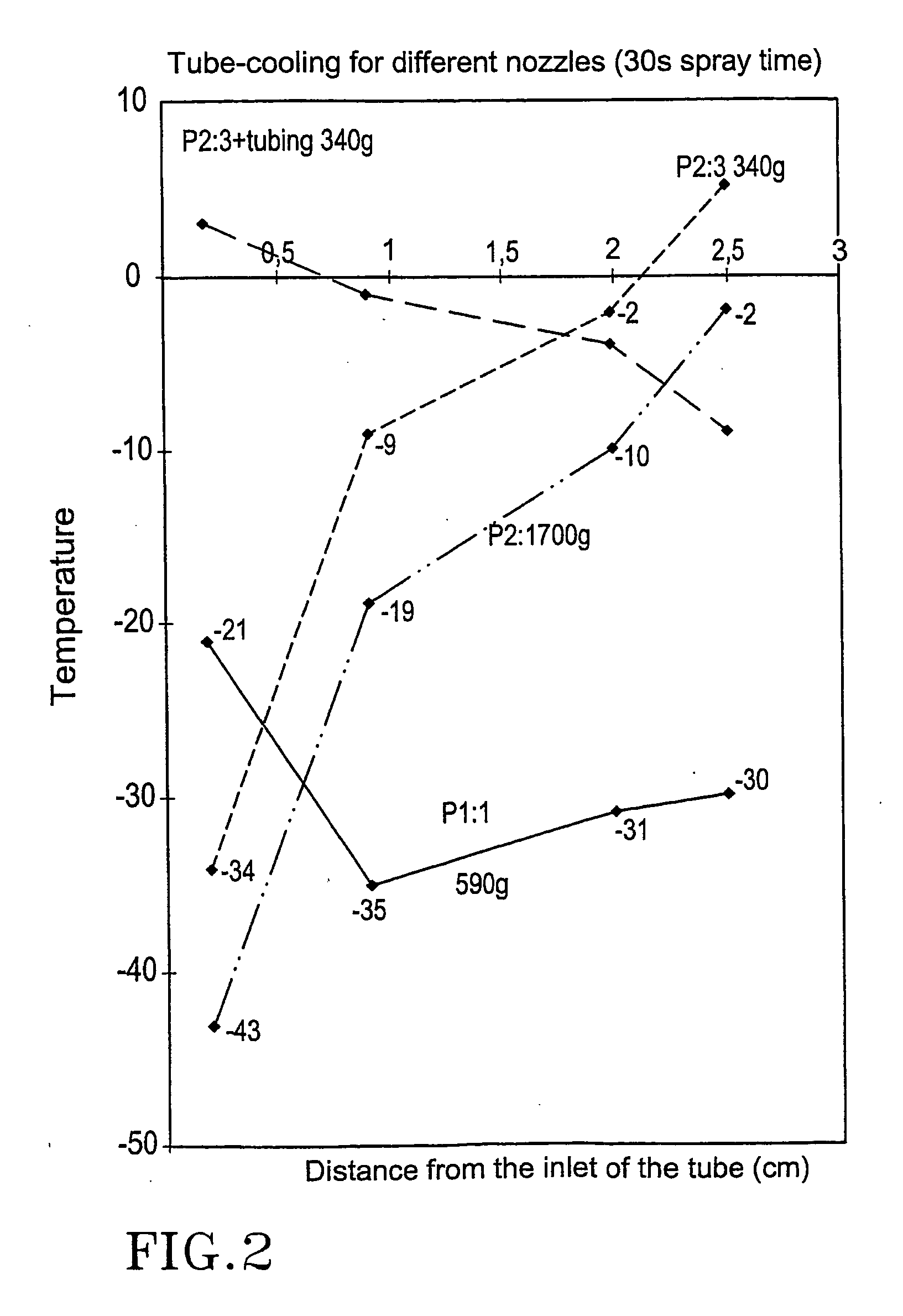
[0059] The tube has a internal diameter of 45 mm and a goods thickness of 4 mm. The total length is about 2.5 m. The first 90° bend is located 1.87 m on the tube and the other bend is bended 90° 0.5 m after the first bend. The tube is turned so that the first bend is faced upwards. The thermo elements are brought on plastic pieces on the internal surface exhibiting the distances of 0.215 m and 0.870 m from the inlet of the straight portion of the tube. The third thermo element was brought just after the first bend and the fourth thermo element in the second bend. The thermo elements were denoted K 1, K3, K9 and K11.

[0060] Tables 1-7 below show cooling inside tubes. FIG. 2 is a graph showing cooling inside a tube for the different nozzles at different distances from the opening of the tube. FIG. 5 shows the comparison between a nozzle, P2:3, at different spraying times. Table 1.

TABLE 1Represents cooling inside tubes. Nozzle P1:1. S...

example 2

[0068] Tests in a Wedge.

[0069] Two aluminium panels 400 mm×100 mm are brought against each other as to form a wedge having an opening of 1 mm on top and 0 mm in the bottom. The panel thickness is 1 mm. The panels belly outwards a bit when they are subjected for the pressure of the carbon dioxide. The thermo elements are brought on the surface without contact with the panel in recessed holes 3 mm. The lower and the upper measure point are brought 5 mm from the respective edge and the third in the middle. The measure points are denoted K1, K3 and K9 from the surface to the bottom.

[0070] The Tables 8-11 below show cooling in a wedge. FIG. 3 is a graph showing cooling in a wedge for the different nozzles at different depths in said wedge.

TABLE 8Cooling in a wedge. Nozzle P1:1. Distance 60 mm, from theside. The wedge is mounted having its longitudinal axis verticallyarranged. Spraying time 3 seconds. Starting temperatureapprox. 25° C. Amount of gas 59 g.TemperatureMeasureMinimumchang...

example 3

Tests on a Planar Surface.

[0075] An aluminium panel having the dimensions of 30×30×0.5 mm was provided with a thermo element that was adhesively joined to the surface in one of the corners. The panel was heat insulated by applying a cell rubber tape on the back.

[0076] The Tables 12-15 show cooling on a planar surface. The cooling effect for different kinds of nozzles on different distances from the target. Table 16 shows cooling of a planar surface. Same nozzle but at different spraying times. FIG. 4 is a graph showing cooling on a planar surface for the different nozzles at different distances from said nozzle and the planar surface.

TABLE 12Cooling on a planar surface. Nozzle P2: 3. Distance 1, 5, 10, 15,20, 30 and 40 cm. Spraying time 3 s. Target: isolated aluminiumpanel. Starting temperature about 25° C. before a newapplication. Used amount of gas 34 g.Distance nozzle-Obtained minimumTemperature° C. / usedtarget (cm)temperature ° C.changeamount of gas (g)1−46712.085−30551.6110...


PUM

PropertyMeasurementUnit
particle sizeaaaaaaaaaa
particle velocityaaaaaaaaaa

Abstract

The present invention relates to a device for the extermination of pests like e.g., worms and arthropods such as insects and wood-louses, mites, etc., wherein said device is provided with a nozzle arranged to distribute carbon dioxide in solid state to create an atmosphere comprising of carbon dioxide and wherein said nozzle is adapted to achieve a predetermined particle size and velocity of said carbon dioxide adapted for the geometry the pest is located into and wherein the particle size and the velocity are optimized for an effective extermination of the pest in question. The invention also relates to methods and compositions for use with said devices.

Description

TECHNICAL FIELD [0001] The present invention relates to a device for the extermination of pests such as for example worms and arthropods; such as insects and wood-louses, mites, etc., using carbon dioxide of a controlled particle size. The invention also relates to a methods and a composition for use with said device. BACKGROUND OF THE INVENTION [0002] Disinfection by cooling is a well-documented method (Skytte, T. “Bekaempelse af museumskadedyr ved nedfrysning” Naturhistorisk museum, *rhus 1993). The efficiacy is increased if the temperature is allowed to fall very rapidly to very low temperatures. The velocity of the temperature decrease and the achieved minimal temperature are both essential criteria that must act in order to obtain a safe disinfection. [0003] Indoor insects often settles in locations exhibiting of complicated geometries. Some of these areas are not possible to disinfect using conventional methods due to poison related risks or because they are out of reach for t...

Claims


Application Information

Patent Timeline
Patent Type & Authority Applications(United States)
IPC IPC(8): A01M1/20A01M17/00A01M25/00
CPCA01M1/2055A01M1/2094A01M2200/011A01M25/006A01M25/008A01M17/002
Inventor ELIASSON, BERTIL
Owner CTS RTECH
Learn More