Magnetic field generating device and mri equipment using the device

a magnetic field and generating device technology, applied in the direction of magnetic bodies, instruments, using reradiation, etc., can solve the problems of reducing the efficiency of the magnetic circuit and the reduction of the intensity of the magnetic field generated in the magnetic field generation space, so as to improve the intensity of the magnetic field and achieve clearer images

Inactive Publication Date: 2005-07-14
SUMITOMO SPECIAL METAL CO LTD
View PDF5 Cites 6 Cited by
  • Summary
  • Abstract
  • Description
  • Claims
  • Application Information

AI Technical Summary

Benefits of technology

[0006] According to the present invention, the ferromagnetic material which has a large relative permeability is provided near the magnetic field generation space at a place passed by a magnetic flux, whereby it becomes possible to introduce magnetic fluxes sufficiently into the magnetic field generation space, and to improve efficiency of the magnetic circuit. Therefore, it is possible to increase magnetic field intensity generated in the magnetic field generation space.
[0022] Further, by using one of the magnetic field generators described above, it is possible to manufacture an MRI apparatus which is capable of obtaining a clearer image.

Problems solved by technology

In this magnetic field generator, due to a fact that relative permeability of permanent magnets is close to 1, it is sometimes impossible to sufficiently introduce the magnetic flux generated by the second magnetic circuit into the magnetic field generation space, leading to decreased efficiency of the magnetic circuit and reduced intensity of the magnetic field generated in the magnetic field generation space.

Method used


Image

  • Magnetic field generating device and mri equipment using the device
  • Magnetic field generating device and mri equipment using the device
  • Magnetic field generating device and mri equipment using the device

Examples


Embodiment Construction

[0048] Hereinafter, embodiments of the present invention will be described with reference to the drawings.

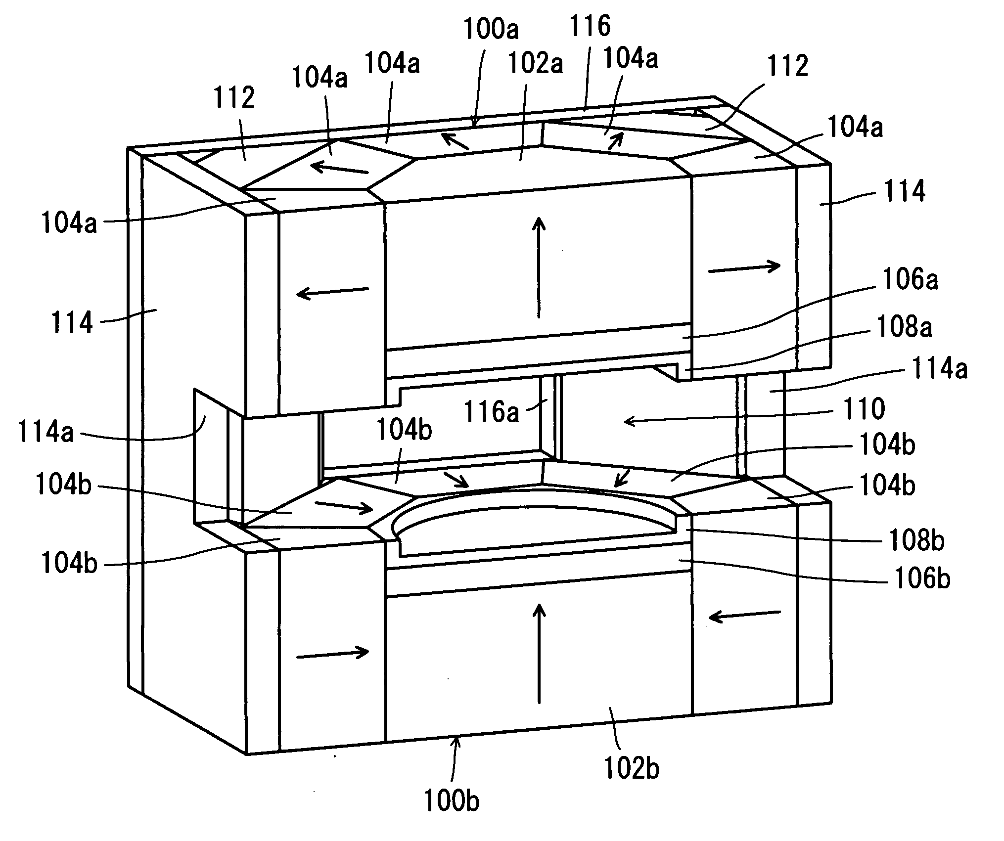
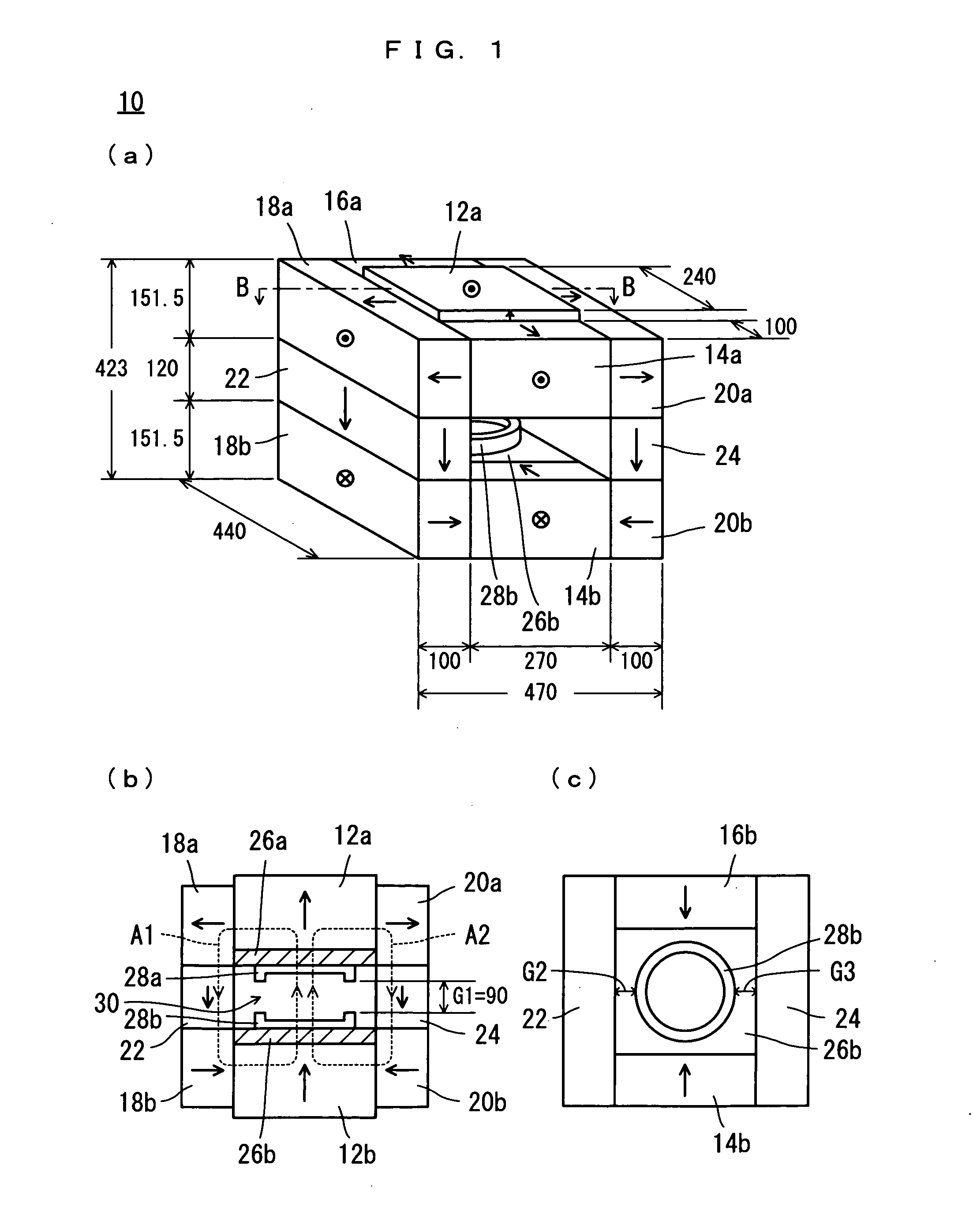
[0049] Referring to FIG. 1(a) through FIG. 1(c), a magnetic field generator 10 as an embodiment of the present invention is formed generally into a parallelepiped using a plurality of parallelepiped permanent magnets, and has outer dimensions of 470 mm×440 mm×423 mm for example. Note that FIG. 1(b) is a conceptual diagram illustrating a section (a longitudinal section passing an upper surface of a permanent magnet 12a) taken in lines B-B in FIG. 1(a).

[0050] The magnetic field generator 10 includes a pair of parallelepiped permanent magnets 12a and 12b.

[0051] Parallelepiped permanent magnets 14a, 16a, 18a and 20a are provided around (on side faces of) the permanent magnet 12a respectively. The permanent magnet 12a makes contact and is magnetically connected with permanent magnets 14a, 16a, 18a and 20a. Under this state, the permanent magnets 14a and 16a are opposed to each oth...


PUM


Abstract

A magnetic field generator (10) capable of generating a more intense magnetic field, and an MRI apparatus (200) using it are provided. Permanent magnets (12a), (12b), (14a), (14b), (16a), (16b), (18a), (18b), (20a), (20b), (22) and (24) are disposed annularly for formation of a magnetic field generation space (30). Ferromagnetic materials (26a) and (26b) are provided near the magnetic field generation space (30), at places passed by a magnetic flux. Each of the permanent magnets (12a), (14a), (16a), (18a) and (20a) surrounding the ferromagnetic material (26a) is magnetized so as to make an S pole on the side of the ferromagnetic material (26a). Each of the permanent magnets (12b), (14b), (16b), (18b) and (20b) surrounding the ferromagnetic material (26b) is magnetized so as to make an N pole on the side of the ferromagnetic material (26b). An MRI apparatus (200) is obtained by using the magnetic field generator (10).

Description

TECHNICAL FIELD [0001] The present invention relates to a magnetic field generator and an MRI apparatus using it. More specifically, the present invention relates to a small, permanent-magnet-type magnetic field generator and an MRI apparatus utilizing it, for diagnosis of body parts such as a finger, small animals, inside of food. BACKGROUND ART [0002] The applicant of the present patent application has proposed a magnetic field generator of this kind in JP-A 2001-70280. The magnetic field generator includes a first magnetic circuit which is a closed circuit provided by magnets, and a second magnetic circuit provided by attaching magnets which are magnetized in a direction perpendicular to the direction of magnetic flux of the first magnetic circuit, to the magnets that provide the first magnetic circuit. The magnetic field generator is characterized by that the two magnetic fluxes, one generated by the first magnetic circuit and the other generated by the second magnetic circuit, ...

Claims


Application Information

Patent Timeline
IPC IPC(8): G01R33/38G01R33/383
CPCG01R33/383G01R33/3806
Inventor AOKI, MASAAKITSUZAKI, TSUYOSHI
Owner SUMITOMO SPECIAL METAL CO LTD
Why Eureka
Try Eureka