
Device, method, and system for controlling fluid flow

a technology of fluid flow and fluid flow, applied in liquid/fluent solid measurement, process and machine control, instruments, etc., can solve the problems of flow rate drift and/or fluctuation outside the required tolerance, limited flow rate range, and low repeatability and set point accuracy of conventional arrangements

Inactive Publication Date: 2005-07-14
BOC EDWARDS
View PDF14 Cites 47 Cited by
  • Summary
  • Abstract
  • Description
  • Claims
  • Application Information

AI Technical Summary

Benefits of technology

[0007] In the following description, certain aspects and embodiments of the present invention will become evident. It should be understood that the invention, in its ...

Problems solved by technology

Some conventional fluid flow controlling arrangements are generally large devices with limited flow rate ranges.
Further, some conventional arrangements may have relatively low repeatability and set point accuracy.
In some instances, variations in upstream liquid delivery pressures (e.g., pulsations) may cause flow rates to drift and / or fluctuate outside of required tolerances.
In addition, certain liquid delivery conditions—such as flow resistance, partially filled delivery lines, and suction—may also degrade flow control capability.
Furthermore, a lack of sufficient responsiveness associated with some configurations may cause an overshoot, undershoot, and / or inadequate batch volume control of one or more fluids.

Method used


Image

  • Device, method, and system for controlling fluid flow
  • Device, method, and system for controlling fluid flow

Examples


Embodiment Construction

[0024] Reference will now be made in detail to a few exemplary embodiments of the invention. Wherever possible, the same reference numbers are used in the drawings and the description to refer to the same or like parts.

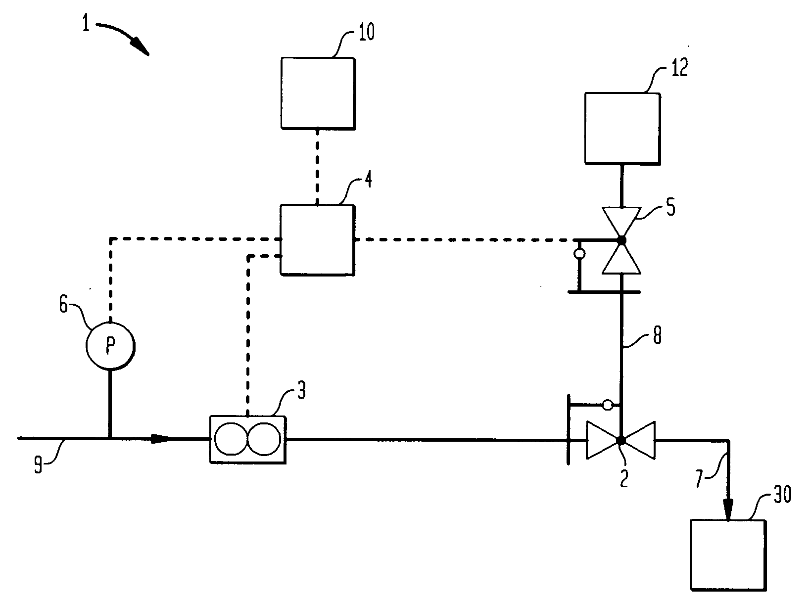
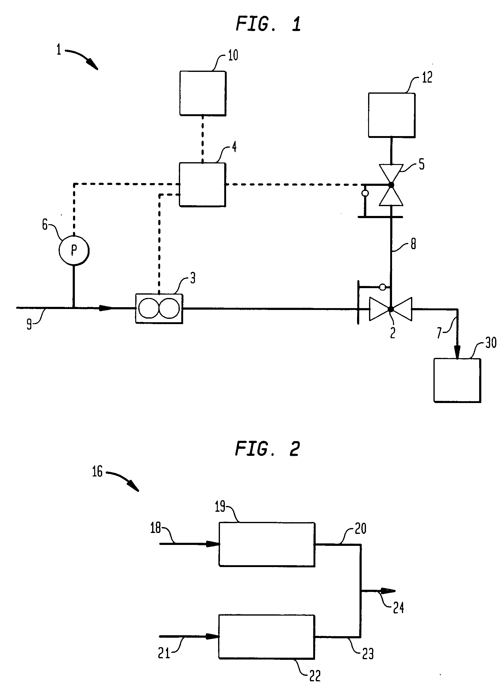
[0025]FIG. 1 shows an embodiment of a flow control device 1. Fluid, such as a liquid, slurry, gas, and / or mixture thereof, enters the device 1 via a fluid inlet 9. As described in more detail below, a fluid flow control valve 2 adjusts the flow rate of fluid exiting the device 1 via a fluid outlet 7.

[0026] In the embodiment of FIG. 1, the fluid flow control valve 2 is a pneumatically actuated valve that adjusts the flow rate of the fluid according to an amount of pneumatic pressure supplied to the pneumatic port of the fluid flow control valve 2. As shown in FIG. 1, the device 1 also includes a flow meter 3, a controller 4, and a pneumatic pressure controlling portion 5 supplying controlled pneumatic pressure to the flow control valve 2 via a line 8. Flow meter 3 me...


PUM


Abstract

A flow control device may include an inlet for passing fluid into the device, an outlet for passing fluid from the device, a pneumatic pressure controlling portion, a fluid flow control valve actuated by pneumatic pressure supplied via the pneumatic pressure controlling portion, a flow meter configured to measure flow rate of the fluid, and a controller configured to control the pneumatic pressure controlling portion at least according to the flow rate measured by the flow meter. Actuation of the fluid flow control valve may cause adjustment of the flow rate.

Description

[0001] This application claims priority to U.S. Provisional Patent Application Ser. No. 60 / 534,590 filed Jan. 6, 2004.BACKGROUND OF THE INVENTION [0002] 1. Field of the Invention [0003] The present invention relates to a device, method, and system for controlling the flow rate of a fluid. Some exemplary aspects of the invention may relate to a flow control device for semiconductor processing tools. [0004] 2. Description of the Related Art [0005] Some conventional fluid flow controlling arrangements are generally large devices with limited flow rate ranges. Further, some conventional arrangements may have relatively low repeatability and set point accuracy. In some instances, variations in upstream liquid delivery pressures (e.g., pulsations) may cause flow rates to drift and / or fluctuate outside of required tolerances. In addition, certain liquid delivery conditions—such as flow resistance, partially filled delivery lines, and suction—may also degrade flow control capability. Furthe...

Claims


Application Information

Patent Timeline
IPC IPC(8): G01F1/00G05D7/00G05D7/06G05D16/18
CPCG05D7/005Y10T137/7759G05D7/00
Inventor FORSHEY, RANDY
Owner BOC EDWARDS
Learn More