Eureka AIR delivers breakthrough ideas for toughest innovation challenges, trusted by R&D personnel around the world.

Bileaflet prosthetic valve and method of manufacture

Inactive Publication Date: 2005-07-07
MEDTRONIC INC
View PDF22 Cites 247 Cited by
  • Summary
  • Abstract
  • Description
  • Claims
  • Application Information

AI Technical Summary

Benefits of technology

[0013] One aspect of the present invention relates to a prosthetic valve including a body, a first leaflet, and a second leaflet. The first leaflet extends across and is coupled to the body. The first leaflet is cut from a first porcin

Problems solved by technology

Any heart valve can be subjected to or incur damage that requires the valve to be repaired or replaced.
Moreover, the conventional tri-leaflet prosthetic valves do not incorporate redundant coaptation while closed and, therefore, such prosthetic valves are not specifically designed to withstand the higher pressures and longer closure periods experienced by the mitral valve.
As such, the anatomy of the prosthetic valves typically used to replace a mitral valve do not sufficiently replicate the native mitral valve anatomy.
However, similar to the conventional stented valves, conventional stentless valves are not constructed or modified to withstand relatively high pressures and prolonged closing intervals.

Method used


Image

  • Bileaflet prosthetic valve and method of manufacture
  • Bileaflet prosthetic valve and method of manufacture
  • Bileaflet prosthetic valve and method of manufacture

Examples


Embodiment Construction

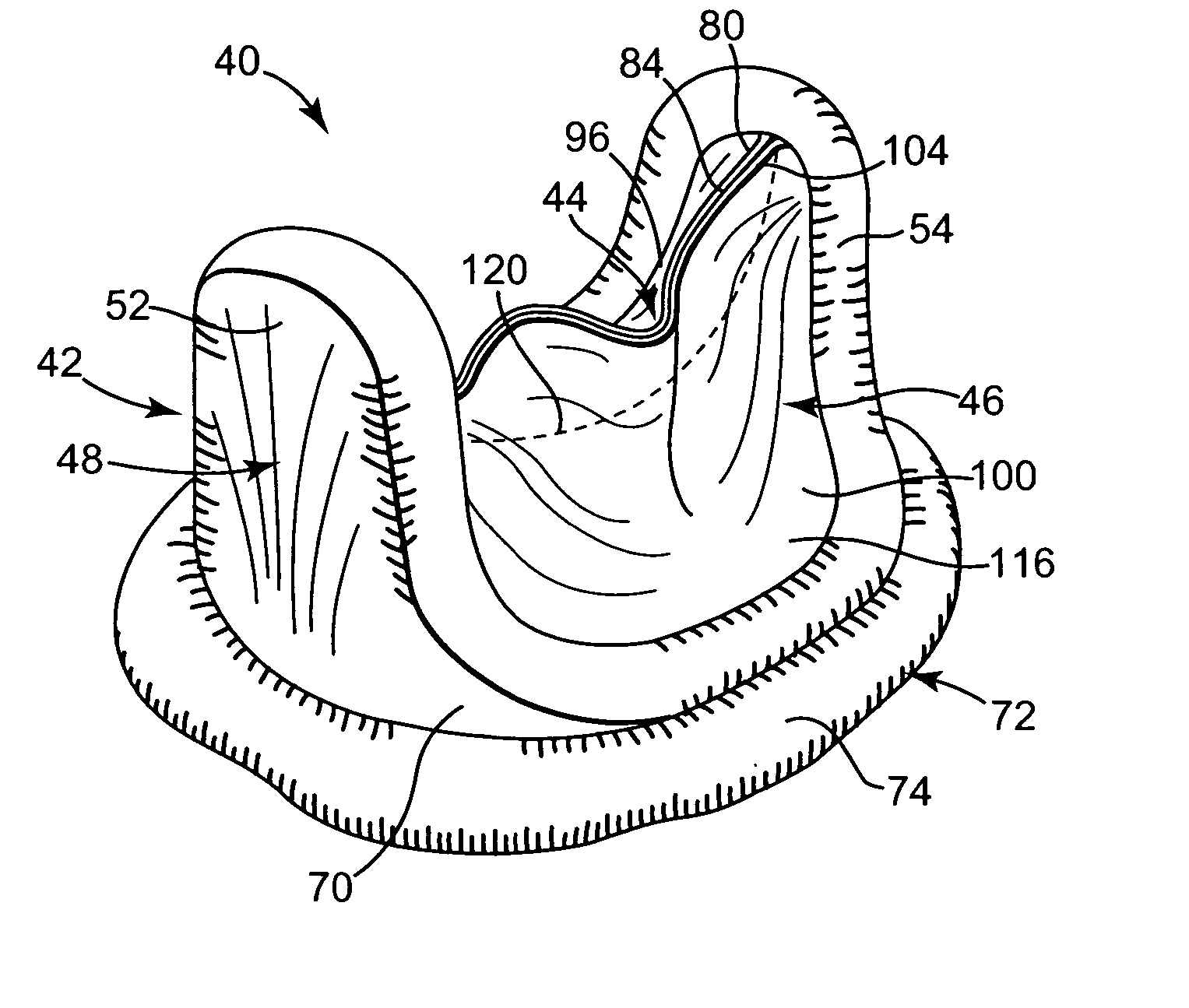
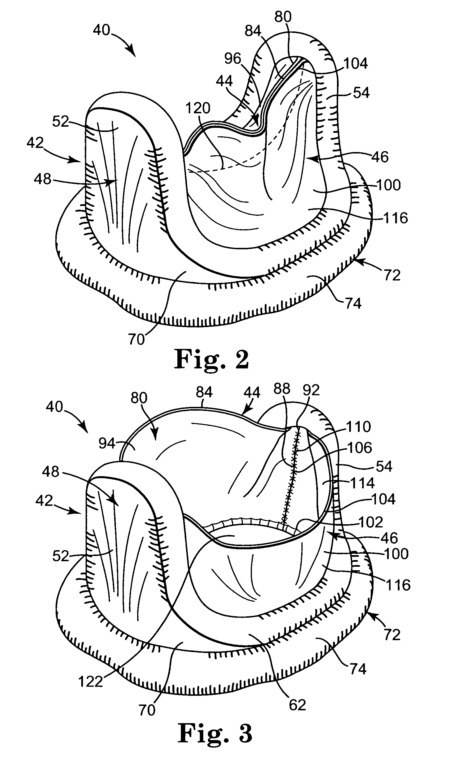
[0026] One preferred embodiment of a bileaflet, prosthetic valve 40 in accordance with the present invention is illustrated in FIGS. 2 and 3. The prosthetic valve 40 includes a body 42, a first leaflet 44, and a second leaflet 46. The body 42 serves as the support structure to which the first leaflet 44 and the second leaflet 46 are opposingly attached. In particular, the leaflets 44 and 46 are attached such that in a closed position, as illustrated in FIG. 2, the first leaflet 44 interacts with the second leaflet 46 to close the prosthetic valve 40. More precisely, the first leaflet 44 and the second leaflet 46 redundantly coapt to close and to prevent blood flow through the prosthetic valve 40 prosthetic valve 40. When open, as illustrated in FIG. 3, the first leaflet 44 and the second leaflet 46 are pulled away from one another, thereby opening the prosthetic valve 40 to allow blood flow to freely pass through the prosthetic valve 40.

[0027] As illustrated in FIG. 4, in one embod...


PUM


Abstract

A prosthetic valve including a body, a first leaflet, and a second leaflet. The first leaflet extends across and is coupled to the body. The first leaflet is cut from a first porcine aortic valve and defines a first inner surface. The second leaflet extends across and is coupled to the body opposite the first leaflet. The second leaflet is cut from a second porcine aortic valve and defines a second inner surface.

Description

BACKGROUND OF THE INVENTION [0001] The present invention relates to an implantable prosthetic valve. More particularly, the present invention relates to a bileaflet implantable prosthetic valve with redundant coaptation to be implanted during heart valve replacement surgery. [0002] There are four valves of the heart, the mitral valve, the aortic valve, the tricuspid valve, and the pulmonary valve. Anatomically and generally speaking, each valve forms or defines a valve annulus and valve leaflets. Although similar in general function, the mitral valve differs significantly in anatomy from the other valves, in particular, the aortic valve. The annulus of the mitral valve is somewhat “D” shaped or elongated whereas the annulus of the aortic valve is more nearly circular. Furthermore, the mitral valve includes two leaflets that are oval or “D” shaped, in contrast to the aortic valve, which includes three leaflets that are more nearly circular. Mitral valves are also subject to higher pr...

Claims


Application Information

Patent Timeline
IPC IPC(8): A61F2/24
CPCA61F2/2412A61F2220/0075A61F2/2415
Inventor EBERHARDT, CAROL E.
Owner MEDTRONIC INC
Why Eureka
Eureka Blog
Learn More