
Method of improving the flow conditions in an axial-flow compressor, and axial-flow compressor for carrying out the method

a compressor and flow condition technology, applied in the field of compressor technology, can solve the problems of narrow compressor working range, limited research on air-jet vortex generators, shock-induced separation of boundary layers,

Inactive Publication Date: 2005-07-07
ALSTOM TECH LTD
View PDF9 Cites 18 Cited by
  • Summary
  • Abstract
  • Description
  • Claims
  • Application Information

AI Technical Summary

Benefits of technology

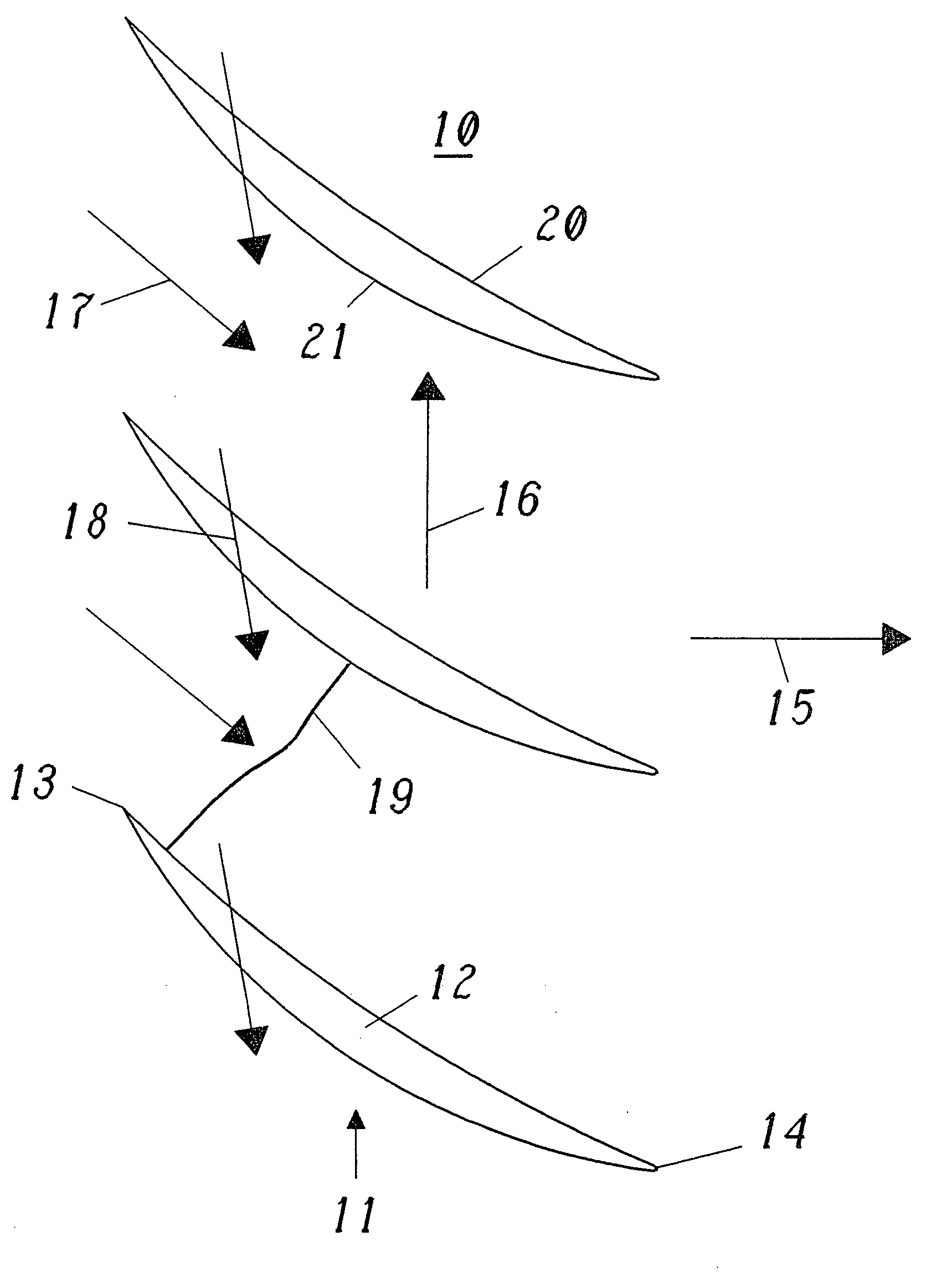
[0007] The object of the invention is to specify a method and an axial-flow compressor with which the flow conditions on the suction side of the blades of the compressor can be improved with regard to the shock stabilization in a reliable and simple manner, in particular without the need for additional built-in components.
[0008] The object is achieved by all the features of claims 1 and 7 in their entirety. The essence of the invention consists in the fact that vortices running on the suction side in the direction of flow are generated by local air jets formed on the suction side. Due to the local air jets, the use of additional elements arranged on the blade surfaces is avoided and the risk of such elements falling off, with the resulting damage to following stages, is removed.
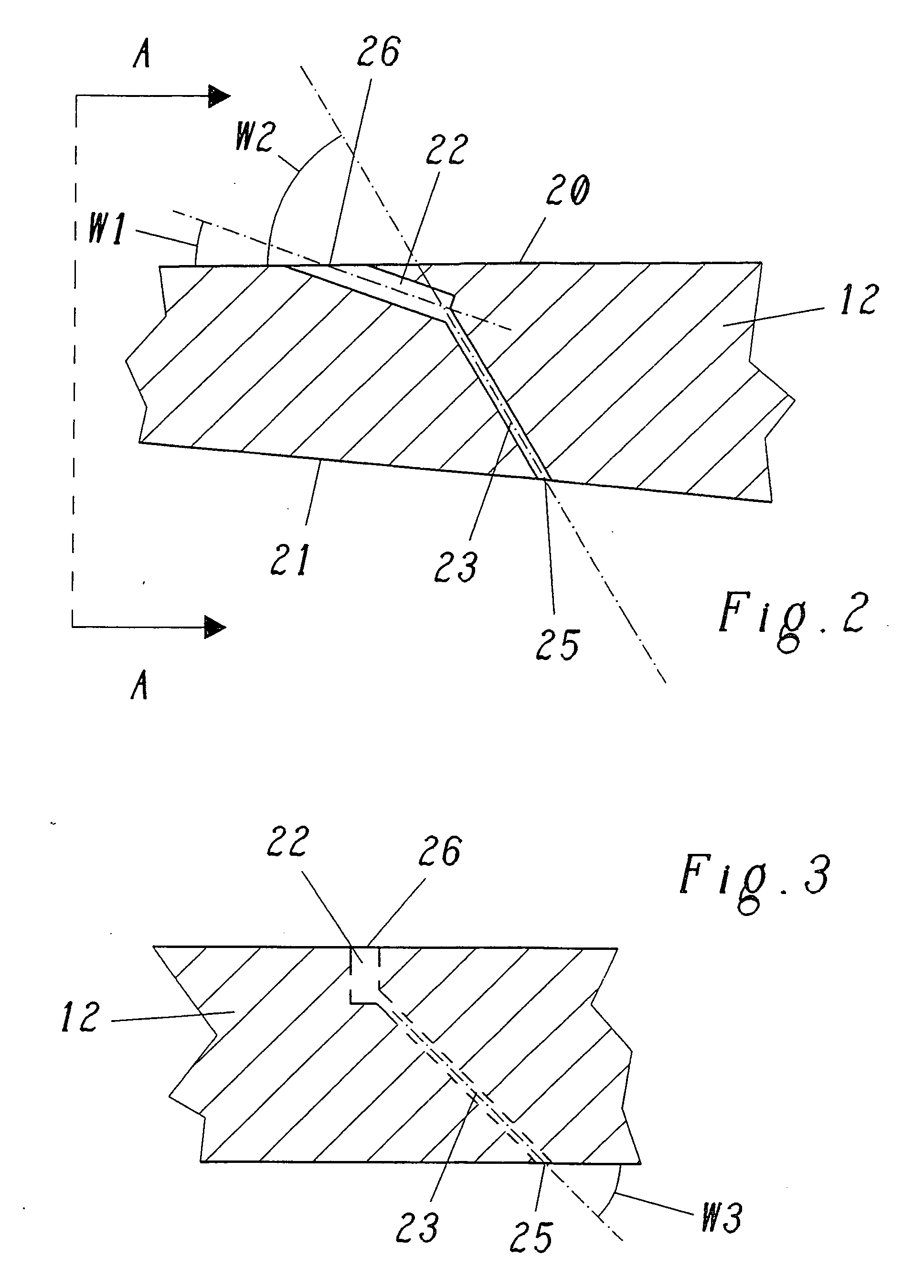
[0009] According to a preferred configuration of the method according to the invention, to form the local air jets, air having a higher pressure relative to the environment is discharged from first openings in the suction-side surface of the blade. It is thereby possible to avoid parts which project from the surface of the blade and adversely affect the flow.
[0010] The method according to the invention becomes especially simple if, according to a preferred development, the air having the higher pressure on the pressure side of the blade is extracted from the flow and is directed through the blade to the first openings in the suction-side surface of the blade. In this way, greatly simplified, automatic generation of air jets is realized, which is distinguished by a minimum space requirement and renders control means arranged outside the compressor unnecessary.
[0011] The method can be carried out especially effectively and with minimum cost if a second opening on the pressure side of the blade is in this case assigned to each first opening on the suction side of the blade, and if the air having the higher pressure is in each case extracted at the second opening and directed via passages in the blade to the associated first opening.

Problems solved by technology

The main problems associated with such high Mach numbers are a shock-induced separation of boundary layers and a very narrowly restricted working range of the compressor (“unique incidence condition”).
In the field of turbomachines, research with regard to air-jet vortex generators is much more limited.
The fact that boundary-layer control by vortex generators in compressors was not mentioned here is certainly connected with the very small blade thickness, which does not allow larger flow mechanisms to be accommodated in the interior of the blade.
In particular, this also means that the space for a plenum from which air would be provided for air-jet vortex generators is very restricted.
Although wing-shaped vortex generators do not absolutely require control mechanisms, they have the great disadvantage that there is always the risk of separation from the surface with said control mechanisms, and this separation would then lead to considerable damage to the following stages.

Method used


Image

  • Method of improving the flow conditions in an axial-flow compressor, and axial-flow compressor for carrying out the method
  • Method of improving the flow conditions in an axial-flow compressor, and axial-flow compressor for carrying out the method
  • Method of improving the flow conditions in an axial-flow compressor, and axial-flow compressor for carrying out the method

Examples


Embodiment Construction

[0007] The object of the invention is to specify a method and an axial-flow compressor with which the flow conditions on the suction side of the blades of the compressor can be improved with regard to the shock stabilization in a reliable and simple manner, in particular without the need for additional built-in components.

[0008] The object is achieved by all the features of claims 1 and 7 in their entirety. The essence of the invention consists in the fact that vortices running on the suction side in the direction of flow are generated by local air jets formed on the suction side. Due to the local air jets, the use of additional elements arranged on the blade surfaces is avoided and the risk of such elements falling off, with the resulting damage to following stages, is removed.

[0009] According to a preferred configuration of the method according to the invention, to form the local air jets, air having a higher pressure relative to the environment is discharged from first openings...


PUM


Abstract

In a method of improving the flow conditions on the suction side (21) of the blade (12) of an axial-flow compressor (10) provided for compressing air, in which method vortices running in the direction of flow are generated on the suction side (21), a marked improvement is achieved in a simple and reliable manner by the vortices being generated by local air jets (18) formed on the suction side (21).

Description

TECHNICAL FIELD [0001] The present invention relates to the field of compressor technology. It relates to a method of improving the flow conditions on the suction side of the blade of an axial-flow compressor provided for compressing air according to the preamble of claim 1. It also relates to an axial-flow compressor for carrying out the method. PRIOR ART [0002] The first stage of the compressor of a gas turbine normally works within the supersonic range. In order to further increase the pressure rise per stage, it is desirable to increase the pre-shock Mach number for a higher pressure ratio. The maximum pre-shock Mach number may increase up to about 1.5. The main problems associated with such high Mach numbers are a shock-induced separation of boundary layers and a very narrowly restricted working range of the compressor (“unique incidence condition”). Ways of improving the flow behavior for such high Mach numbers are therefore constantly looked for. The limiting pre-shock Mach n...

Claims


Application Information

Patent Timeline
Patent Type & Authority Applications(United States)
IPC IPC(8): F01D5/14F04D29/32F04D29/68
CPCF01D5/145F04D29/324F05D2240/127Y02T50/673F05D2250/314F04D29/681F04D29/682F04D29/684Y02T50/60
Inventor DOERFFER, PIOTRHUBRICH, KLAUSKAPPIS, WOLFGANG
Owner ALSTOM TECH LTD
Learn More