
Microphone apparatus, reproducing apparatus, and image taking apparatus

a microphone and reproducing technology, applied in the field of microphone apparatus, reproducing apparatus, image taking apparatus, can solve the problems of not being developed, difficult to find a space for the microphone on the video camera, adverse recording of more unnecessary voices, etc., and achieve the effect of effective direction, excellent sound characteristic of the microphone, and super directivity

Inactive Publication Date: 2005-06-30
SONY CORP
View PDF18 Cites 60 Cited by
  • Summary
  • Abstract
  • Description
  • Claims
  • Application Information

AI Technical Summary

Benefits of technology

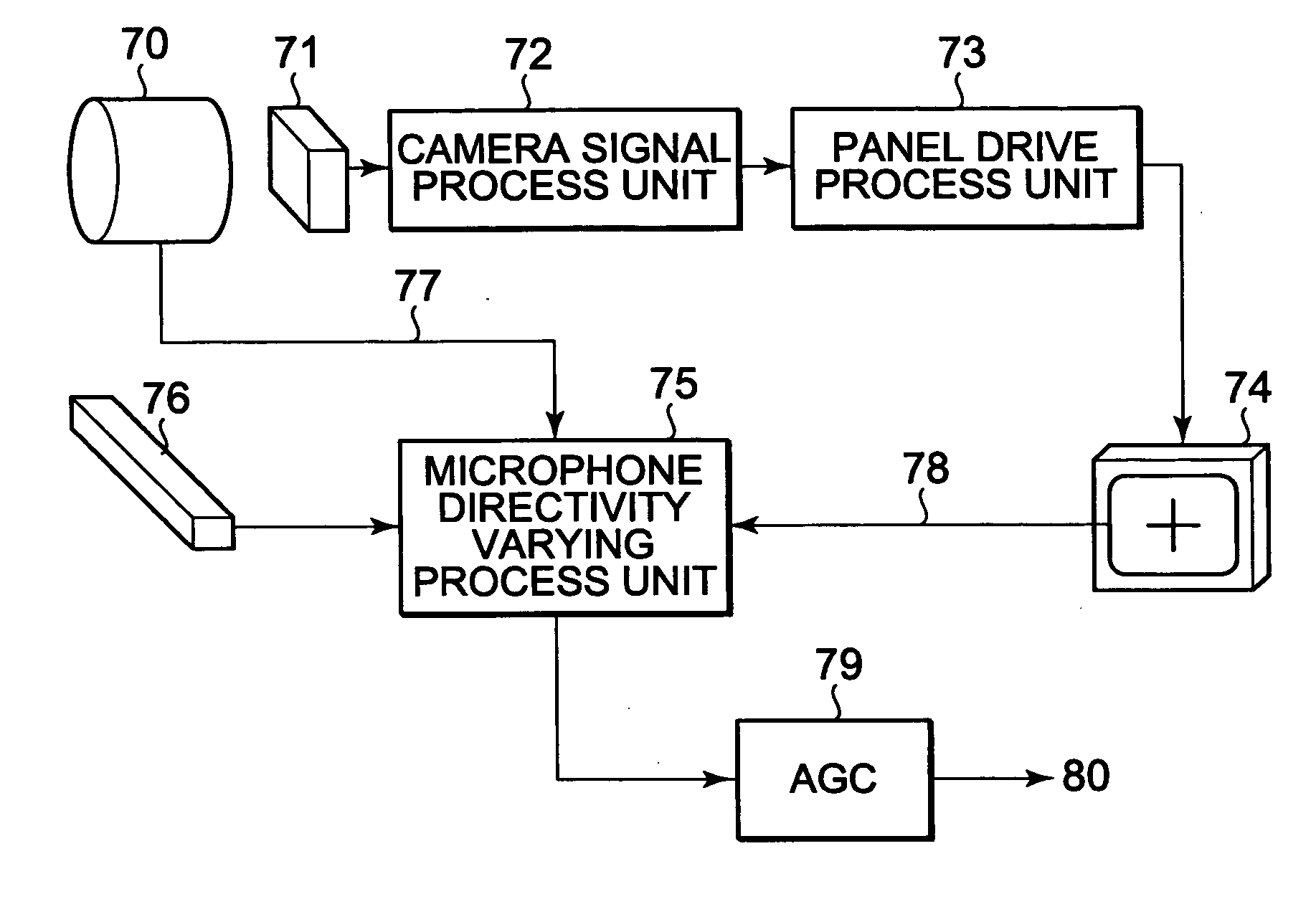
The present invention proposes a new function by combining a pointing device and a microphone. The technology optimizes the sound and voice of an object by directing the microphone towards the position of the object and optimizing the audio level. The technology solves the problem of built-in microphones not being able to optimize sound and voice when imaging and recording pictures. The invention also includes a microphone apparatus with a rotatable panel type view finder and a sound collecting system with multiple microphone units. The technology allows for easy user interface, accurate positioning of real objects, and adjustable output level of the sound or voice.

Problems solved by technology

A technology that selectively optimizes a sound or a voice issued from an object of the picture, and images and reproduces the picture together with the optimized sound or voice has been desired, but such technology has not been developed yet.
It becomes difficult to find a space for the microphone on the video camera, because the video camera is getting smaller.
In this case, more unnecessary voice is adversely recorded than the voice from the target object.
On the other hand, when the microphone is disposed on the front surface of the video camera, the un-smoothness of the front surface having a lens barrel and so forth acoustically shadow the microphone, and this may disturb the acoustic characteristic thereof.
When the microphone protrudes from the body of the video camera, the tradeoff for a good acoustic characteristic is a large size and a low portability of the video camera.

Method used


Image

  • Microphone apparatus, reproducing apparatus, and image taking apparatus
  • Microphone apparatus, reproducing apparatus, and image taking apparatus
  • Microphone apparatus, reproducing apparatus, and image taking apparatus

Examples


Embodiment Construction

[0061] Next, with reference to the accompanying drawings, an embodiment of the present invention will be described. As shown in FIG. 12, most conventional home-use video cameras 121 have a panel type view finder 124 that can be spread out from a closed position that is in parallel with the direction of the optical axis of a zoom lens 123 to an open position that is perpendicular to the direction of the optical axis. The conventional video cameras 121 may not have a conventional eyepiece type view finder 122. The panel type view finder 124 is composed of an LCD (Liquid Crystal Display), a backlight, and so forth. The screen size of the most of the video cameras 121 is in the range from 2.5 to 3.5 inches for high visibility.

[0062] In recent years, the panel type view finder 124 may have provided with a touch panel with which a user can select a picture and an icon to input desired information by touching the display screen with user's finger or a pen. The touch panel of the video cam...


PUM


Abstract

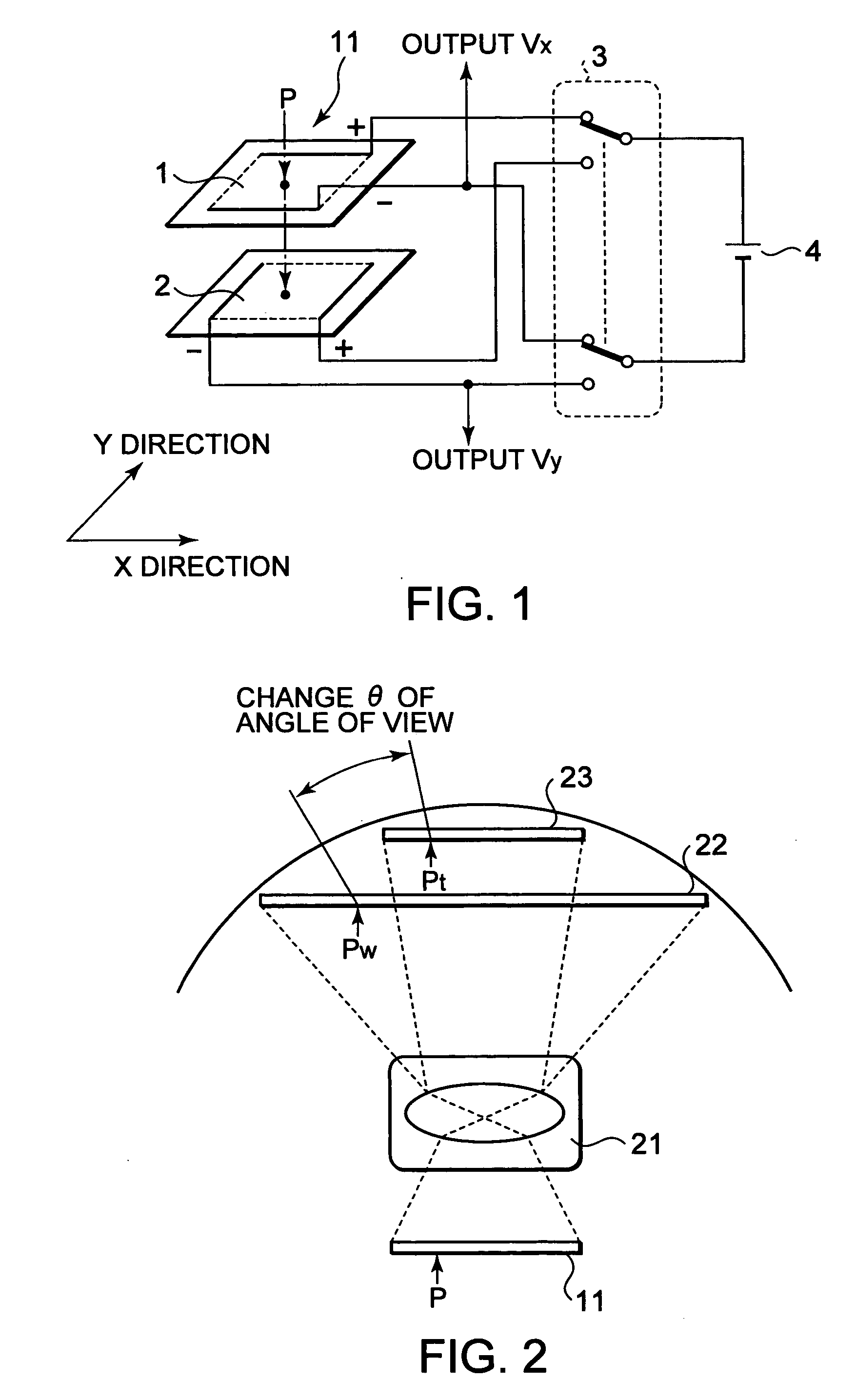
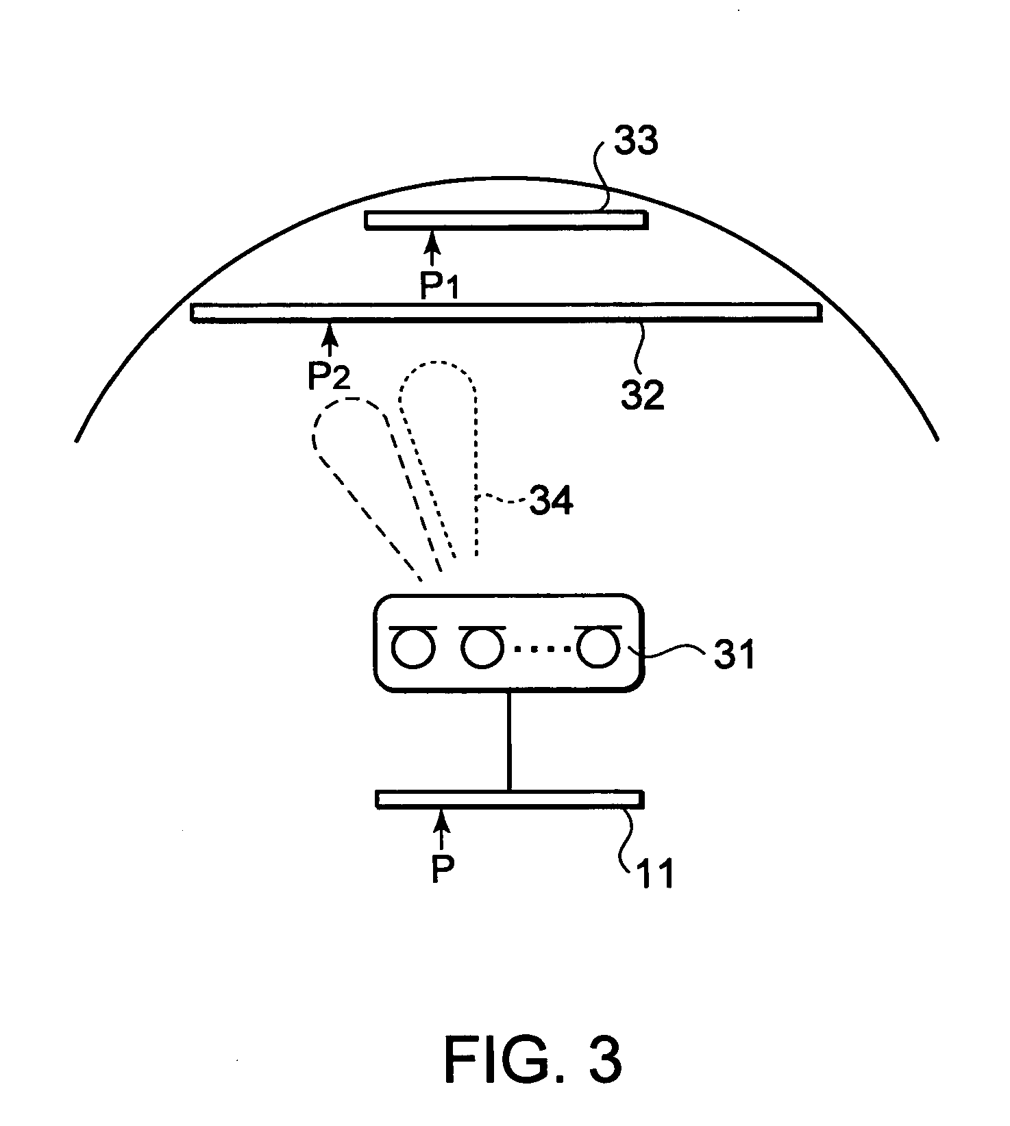
A microphone apparatus of the present invention is applied to a camera including a panel type view finder for displaying a picture taken by the camera, a touch panel for pointing a desired position of the picture displayed on the view finder, determining circuit for determining a direction of the real picture in accordance with the position pointed by the touch panel, a microphone device having a plurality of microphone units for collecting a sound that comes from the picture taken by the camera; and directivity generating circuit for generating a sound directivity signal with which the microphone device collects the sound coming from the direction determined by the determining circuit.

Description

CROSS REFERENCE TO RELATED APPLICATION [0001] This application claims priority from Japanese Priority Document No. 2003-359769, filed on Oct. 20, 2003 with the Japanese Patent Office, which document is hereby incorporated by reference. BACKGROUND OF THE INVENTION [0002] 1. Field of the Invention [0003] The present invention relates to a microphone apparatus, a reproducing apparatus, and an image taking apparatus. [0004] 2. Description of the Related Art [0005] Most of portable video / audio recording and reproducing apparatuses such as video cameras and digital cameras put on a market in recent years have a panel type view finder with which an imaged picture or an imaging picture is monitored. The panel type view finder has a higher visibility than a conventional built-in finder (namely, a view finder through which the user observes an object with an ocular) because the panel type view finder allows the user to easily observe the picture even if he or she is not so close to the panel ...

Claims


Application Information

Patent Timeline
Patent Type & Authority Applications(United States)
IPC IPC(8): H04N5/225H04N5/232H04N101/00H04R1/40H04R3/00H04R5/027
CPCH04N5/23293H04R2430/23H04R2201/403H04R3/005H04R2499/11H04N23/531H04N23/631
Inventor OZAWA, KAZUHIKO
Owner SONY CORP
Learn More