Product identification data management system and product identification data management method

a product identification and data management technology, applied in the field of product identification data management system and method, can solve the problems of inability to obtain detailed information such as the name of the product and its price from the read jan code, inability to attach a tag to the product, and inability to meet the requirements of bar codes, etc., and achieve the effect of efficient data structur

Active Publication Date: 2005-06-30
NEC CORP
View PDF10 Cites 20 Cited by
  • Summary
  • Abstract
  • Description
  • Claims
  • Application Information

AI Technical Summary

Benefits of technology

[0027] As mentioned above, according to the present invention, identification data of two data systems are externally related with each other, the relation therebetween is stored in a database. Accordingly, identification data of one data system need not include all or a part of identification data of the other data system. Since identification data of the two data systems need not depend on each other, the identification data of the two data systems can be independently managed. In addition, identification data itself need not include excess information, thus resulting in efficient data structure.

Problems solved by technology

Unfortunately, detailed information such as the name of the product and its price cannot be obtained from the read JAN code.
Accordingly, bar codes are not suitable for checking the quantity of stock of an item after products of the item are arranged in a showcase.
Regarding the attachment of a tag including identification data of the large-capacity data system to each product, disadvantageously, the tag cannot be attached to the product unless a bar code including identification data of the small-capacity data system has already been attached to the product.
Disadvantageously, the fabrication of tags and the management of identification data are difficult.
Disadvantageously, the dependence between two data systems cannot be eliminated.

Method used


Image

  • Product identification data management system and product identification data management method
  • Product identification data management system and product identification data management method
  • Product identification data management system and product identification data management method

Examples


first embodiment

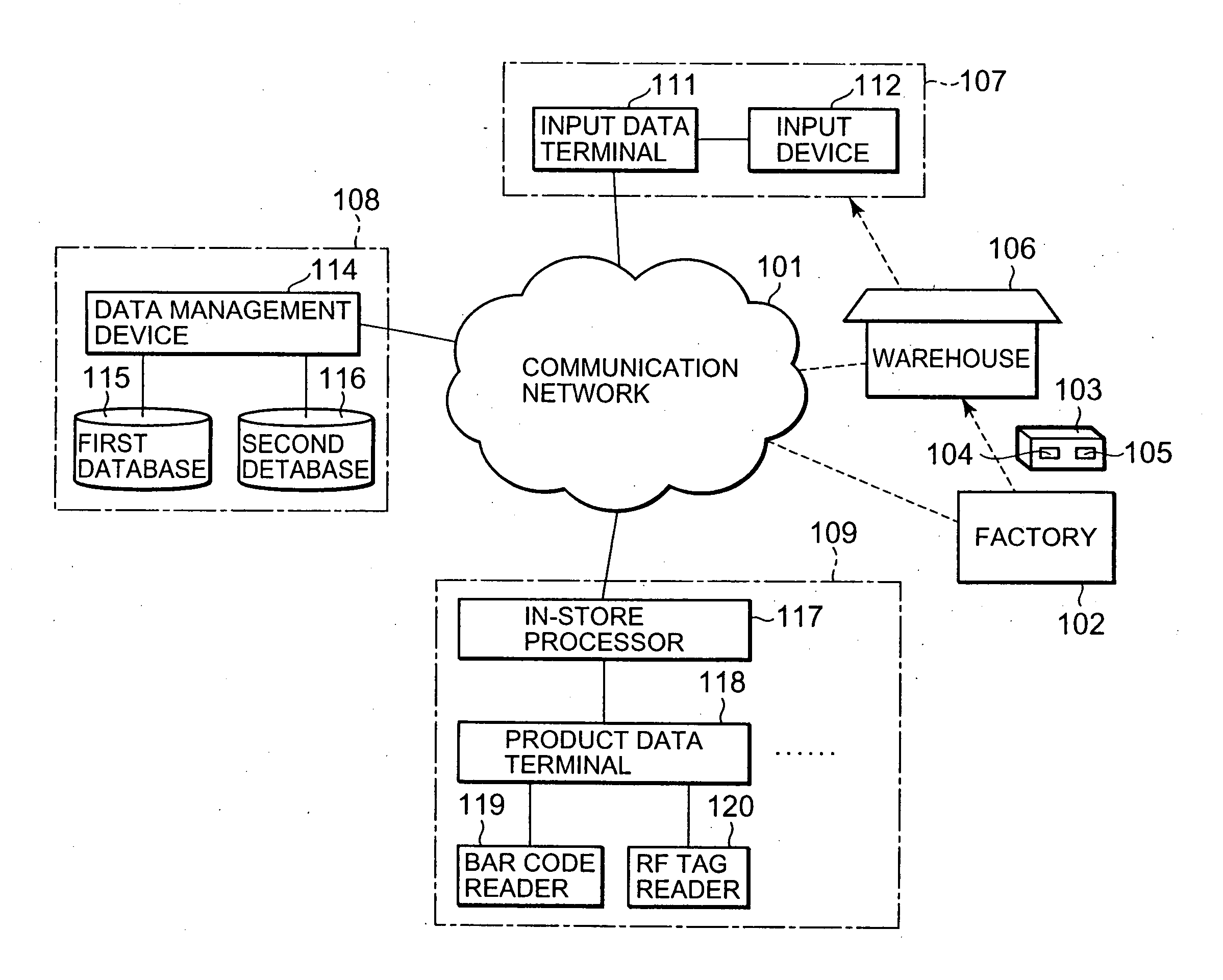
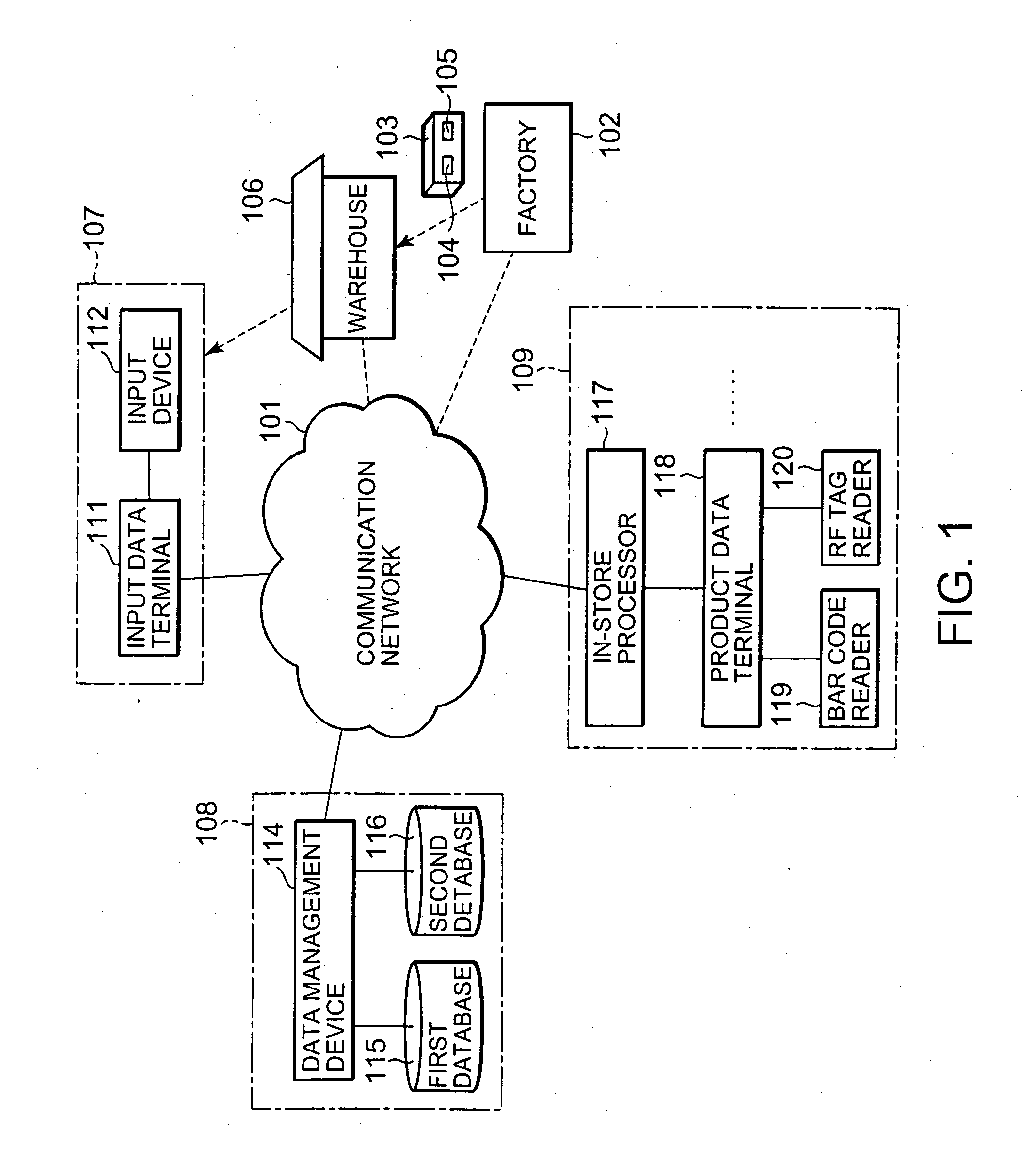
[0050]FIG. 1 shows an overview of a product identification data management system 100 according to a first embodiment of the present invention. The product identification data management system 100 manages products handled in stores of a specific sales company using a communication network 101 such as the Internet or an Intranet. In a factory 102, each of the products 103 is affixed with a bar code 104 indicating a manufacturer code and a product code and an RF tag 105 with identifier whereby the corresponding product can be uniquely identified. Then the products 103 are shipped out. The products 103 are stored in a warehouse 106 and appropriately delivered to a purchasing department 107 of the sales company. The purchasing department 107, an information department 108, and the store of the company 109 are connected to the communication network 101. Although one factory 102, one warehouse 106, one purchasing department 107, and one store 109 are shown in FIG. 1, the arrangement is n...

second embodiment

[0079]FIG. 13 shows the principle structure of an essential part of a product identification data management system 400 according to a second embodiment of the present invention. In FIG. 13, the same components as those in FIG. 3 are designated by the same reference numerals and the description thereof is omitted as appropriate. The entire structure of the product identification data management system 400 according to the second embodiment will be described using FIG. 1 relating to the first embodiment as needed.

[0080] An input-output device 401 has a function for simultaneously reading a bar code and an RF tag and a notifying function for checking the consistency between the class of an EPC, obtained from the read RF tag, and that of bar code data and making an error notification only when a wrong combination of the bar code and the RF tag is affixed on the product.

[0081]FIG. 14 shows the input-output device 401 which is reading identification data of a product 103. The input-out...

third embodiment

[0088]FIG. 16 shows the principle structure of an essential part of a product identification data management system 500 according to a third embodiment of the present invention. In FIG. 16, the same components as those in FIG. 3 are designated by the same reference numerals and the description thereof is omitted as appropriate. The entire structure of the product identification data management system 500 according to the third embodiment will be described using FIGS. 1 and 2 relating to the first embodiment as needed.

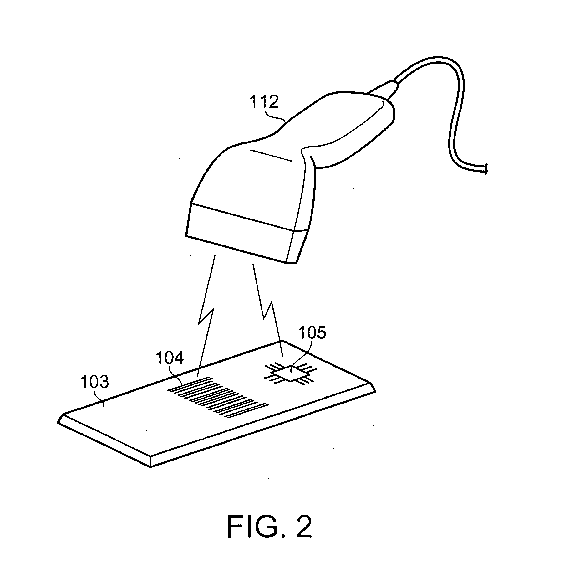
[0089] In the product identification data management system 500, each input device 112 simultaneously reads a bar code and an RF tag as shown in FIG. 2 and supplies bar code data 121 and RF tag data 122 to a relating unit 123B. According to the present embodiment, actually, the input devices 112 are arranged in a factory 102, a warehouse 106, and a purchasing department 107 shown in FIG. 1, respectively. The relating unit 123B allows a first data updating unit 124B to ...


PUM


Abstract

The present invention relates to a product identification data management system and method. According to the present invention, an input device of a purchasing department reads a bar code and an RF tag as data of two identification data systems added to a product such that the identification data of the two identification data systems are related with each other. The read bar code data and RF tag data are stored and managed in first and second databases of a information department, respectively. When a user terminal such as a product data terminal issues a request to acquire predetermined data on the basis of the bar code data of the product, the predetermined data is retrieved from either or both of the first and second databases. The acquired data is returned to the user terminal. The consistency between identification data added to each product can also be checked.

Description

BACKGROUND OF THE INVENTION [0001] 1. Field of the Invention [0002] The present invention relates to a product identification data management system and method for managing identification data attached to products. [0003] 2. Description of the Related Art [0004] Bar codes are affixed on most products dealt with in stores. A bar code is a combination of varying-width parallel bars and spaces and represents numerical data or symbolic data. The bar code is read using a bar code reader as a dedicated input device, so that data of the corresponding product can be obtained. Therefore, data concerned with each product can be rapidly input with accuracy without using an input device such as a keyboard to manually input data. Accordingly, bar codes are attached to many products and are effectively used. [0005] Typical data represented using a bar code affixed on a product includes, for example, JAN (Japanese Article Number) code. The JAN code consists of 13 or 8 digits. The JAN code includes...

Claims


Application Information

Patent Timeline
Patent Type & Authority Applications(United States)
IPC IPC(8): G07G1/00G06F17/30G06K17/00G06K19/07G06Q30/06G06Q50/00G06Q50/10G07G1/12
CPCG06Q90/00G06Q10/087
Inventor SATO, TADASHI
Owner NEC CORP
Why Eureka
Try Eureka