
Portable fence-mountable basketball goal and method

a basketball goal and portable technology, applied in the field of portable basketball goals, can solve the problems of cumbersome and bulky movement, rarely portable prior art solutions, and only inconvenient transportation from one location to another, and achieve the effect of little effor

Inactive Publication Date: 2005-06-23
SMITH ROBERT
View PDF32 Cites 11 Cited by
  • Summary
  • Abstract
  • Description
  • Claims
  • Application Information

AI Technical Summary

Benefits of technology

[0006] The present invention is limited only by the scope of the claims as ultimately allowed in this application, and in no way limited by the prior versions of the claims inserted into this provisional application which are inserted only for purposes of priority and satisfaction of potential foreign filing requirements. This specification discloses an apparatus and method for a portable and repositionable basketball goal. The apparatus is rendered imminently transportable in that it is attachable to any standard chain link fence. The need for a dedicated pole and support base, constructed specifically for the goal, is avoided. The device may be removed, folded down, and transported by a person on foot with little effort. Similarly, its compact design renders the device capable of being carried in sets of multiple goals by a single coach. Thus, an entire training camp can be transported and erected by a single individual with little inconvenience. This will have obvious advantages in locations where security, storage, theft, or space allocations are issues.
[0013] A further exemplary and non-exclusive alternative object of the invention is to provide a tool for such a referenced latch system to ease attachment and reduce the potential for injury.

Problems solved by technology

These prior art solutions are rarely portable in the full sense of the term, being cumbersome and bulky to move.
Accordingly, in practice, such devices are rarely and only inconveniently transported from one location to another, except perhaps from a storage room or closely adjacent locations on a single lot.
None of these prior art solutions allow for a system that is easily transported by a single individual, or that can be readily transported in the trunk of a compact automobile.

Method used


Image

  • Portable fence-mountable basketball goal and method
  • Portable fence-mountable basketball goal and method
  • Portable fence-mountable basketball goal and method

Examples


Embodiment Construction

[0024] The following is a detailed exemplary description of an embodiment of the invention, in a number of its various aspects. Those skilled in the art will understand that the specificity provided herein is intended for illustrative purposes with respect to an exemplary embodiment, only, and is not to be interpreted as limiting the scope of the invention or claims.

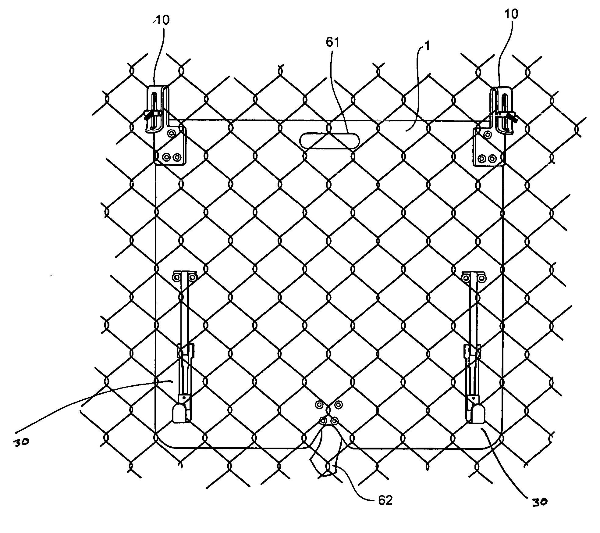
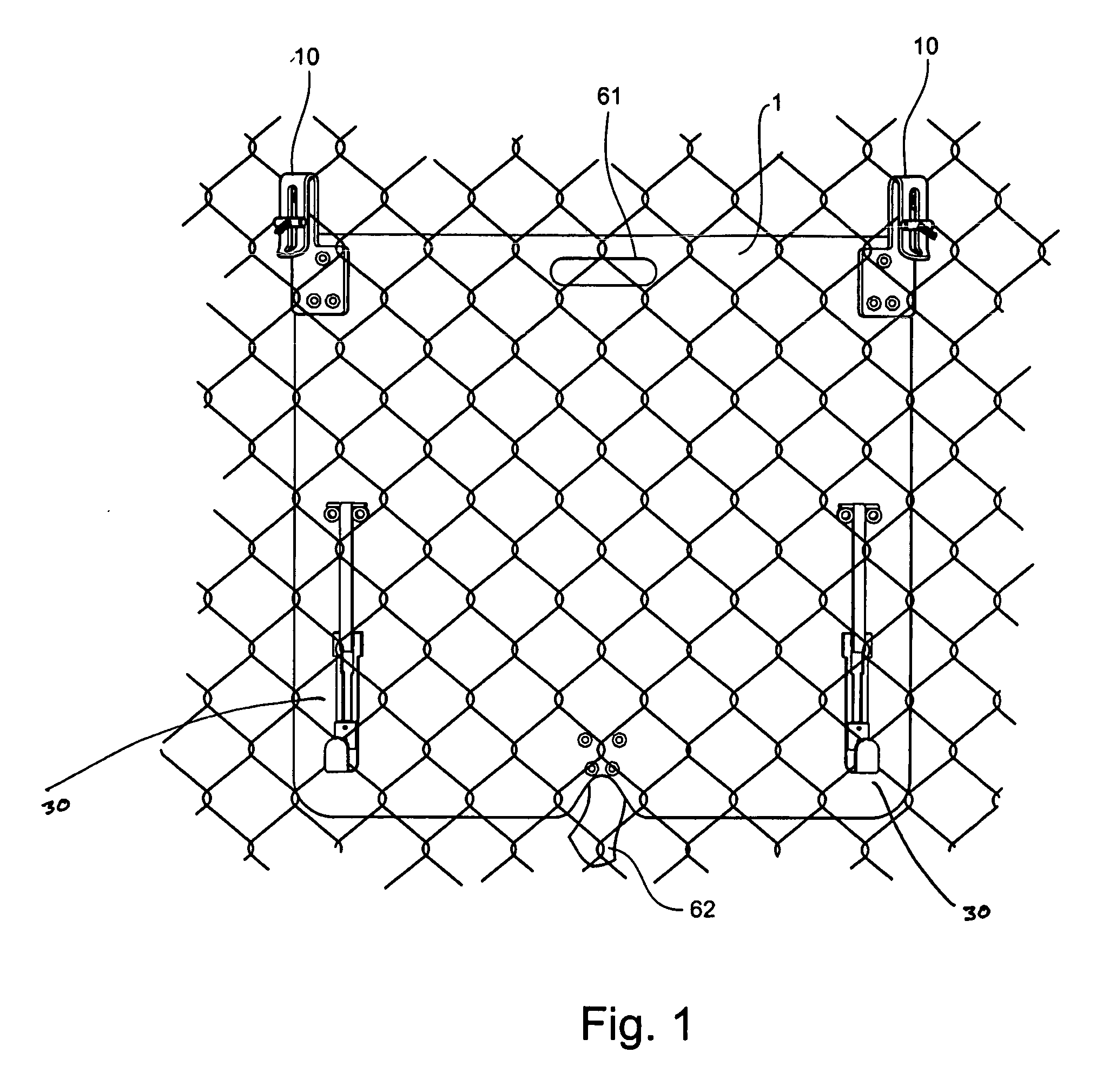
[0025] Turning, now to the drawings, FIG. 1 shows the rear side of a backboard in an embodiment of the present invention, attached to a chain link fence as a support. As will be appreciated in the industry, the chain link fence is not a portion of the invention, but is a readily accessible support that may be found at virtually any location such as school public lots, training grounds, etc., where the invention may be set up for use. Use of such a ready support eliminates the need for users to carry a bulk pole and base.

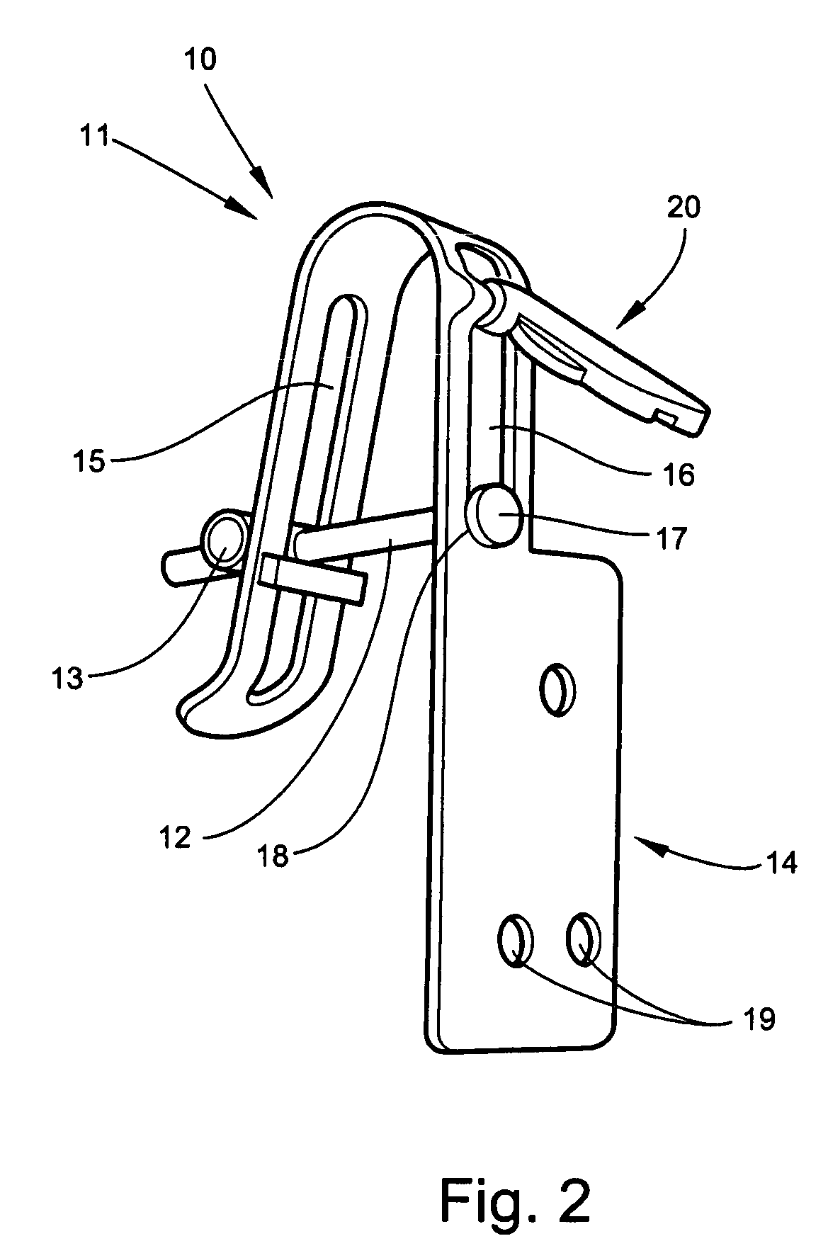
[0026] On the rear of backboard 1 at the upper corners are latches 10. As may be seen from the figur...


PUM


Abstract

The present invention is a device and method variously and separately provided for a transportable backboard and hoop connectable to a chain-link fence as its support structure. Methods of teaching are included. Detail is also provided regarding the methods and structures for attachment of the device to the support structure. The invention is to be limited only by the scope of the claims as ultimately allowed in this application, and in no way limited by the prior versions of the claims inserted into this provisional application which are inserted only for purposes of priority and satisfaction of potential foreign filing requirements.

Description

[0001] This application claims the benefit of and priority to U.S. Provisional Application 60 / 530,401 filed Dec. 17, 2003.BACKGROUND OF THE INVENTION [0002] 1. Field of the Invention [0003] This invention relates generally to an apparatus and method for a portable basketball goal and the attachment and removal of such a goal. More particularly, but without limitation, the invention is directed in one of its embodiments toward a latch system for repositionably attaching a portable basketball goal to a chain-link fence. Additionally, the invention relates to a method for teaching children and persons of short stature basketball techniques and skills. [0004] 2. Description of Related Art [0005] In the art it is known that portable basketball goals are useful to allow the creation of a basketball court on an ad hoc basis. Heretofore, solutions aimed at providing a portable basketball goal assembly have been relatively large, being constructed complete with base, support pole, backboard,...

Claims


Application Information

Patent Timeline
IPC IPC(8): A63B63/08
CPCA63B2208/12A63B63/083
Inventor SMITH, ROBERT
Owner SMITH ROBERT
Learn More