
Automatic voltage device and network protector incorporating same

Active Publication Date: 2005-06-23
EATON INTELLIGENT POWER LIMITED
View PDF7 Cites 5 Cited by
  • Summary
  • Abstract
  • Description
  • Claims
  • Application Information

AI Technical Summary

Benefits of technology

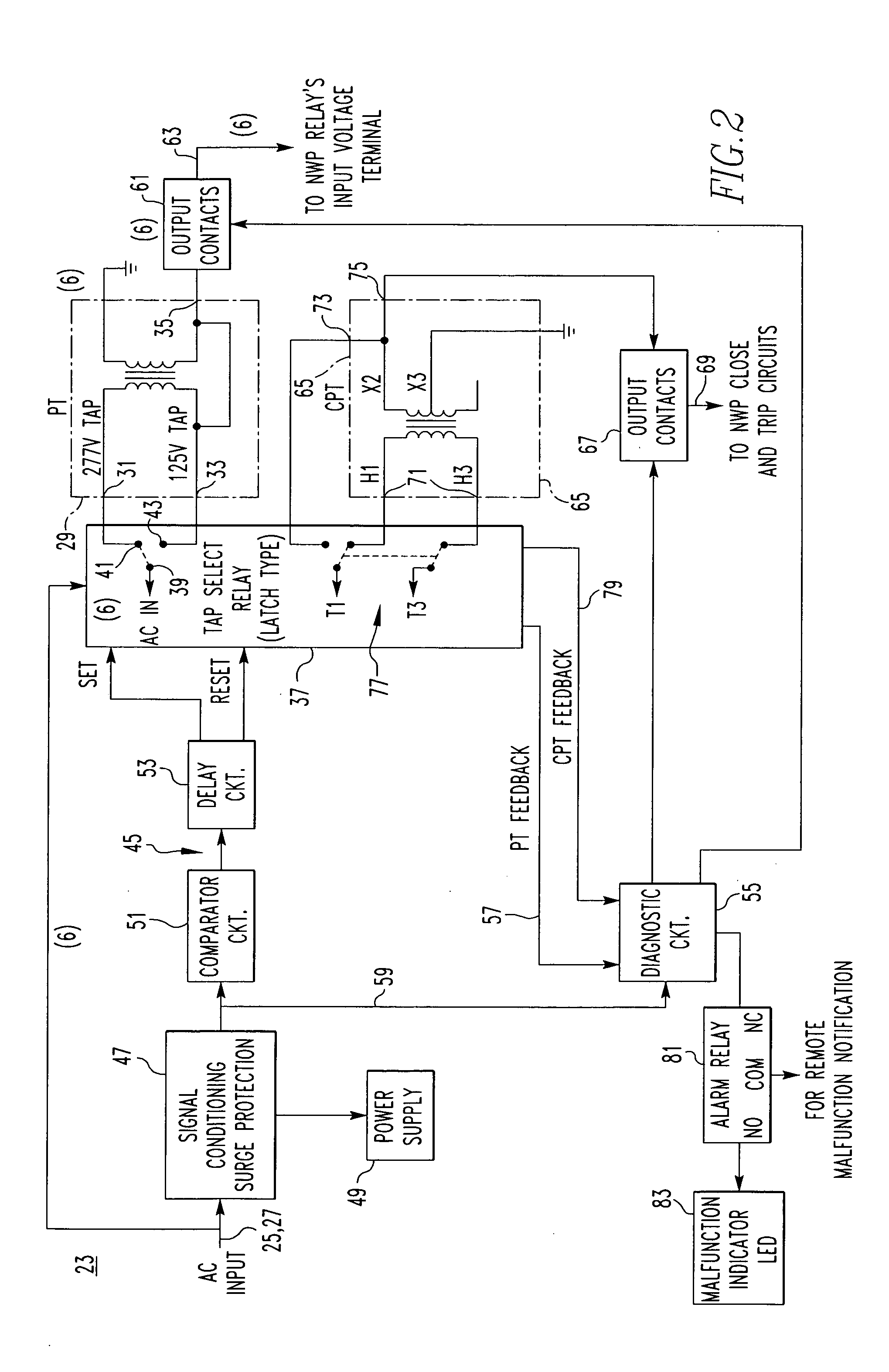
[0011] In a three phase distribution system there are six step down transformers and six input switches which under the operation of the control means connect the three source phase voltages and three network phase voltages to the first or second inputs of the step down transformers.
[0012] The control means also includes output switches between the output taps of the step down transformers and the network protector relay. Diagnostic means monitors the scaled source and network phase voltages and operates the output switch means to connect the output taps to the network protector relay only when all of the scaled source and network phase voltages are of the third operating value. The diagnostic means can also monitor operation of the input switch device and the source and network phase voltages and operate the output switch device only when the position of the switching device means is compatible with the source and network phase voltages.
[0013] The voltage device can also comprise a control step down transformer with first and second input taps and an output tap converting a voltage of the first operating value applied to the first input tap and a voltage of the second operating value applied to the second input tap to a control voltage of a fourth operating value at the output tap for operating the circuit breaker. The control switch selectively connects one of the three source phase voltages and the three network phase voltages to one of the first input taps and the second input tap of the control step down transformer and the control means operates the control switch to connect the one of the source and network phase voltages having the first operating value to the first input tap of the control step down transformer and to connect the one source and network phase voltage having the second operating value to the second input tap of the control step down transformer. The diagnostic means can also monitor the control voltage output by the control step down transformer and to close an output control switch to provide the control voltage to the circuit breaker only when the control voltage has the fourth operating value, which can equal the third operating value.
[0014] In accordance with another aspect o

Problems solved by technology

The control means further comprises delay means delaying switching of the input device for a time interval after power up.

Method used


Image

  • Automatic voltage device and network protector incorporating same
  • Automatic voltage device and network protector incorporating same
  • Automatic voltage device and network protector incorporating same

Examples


Embodiment Construction

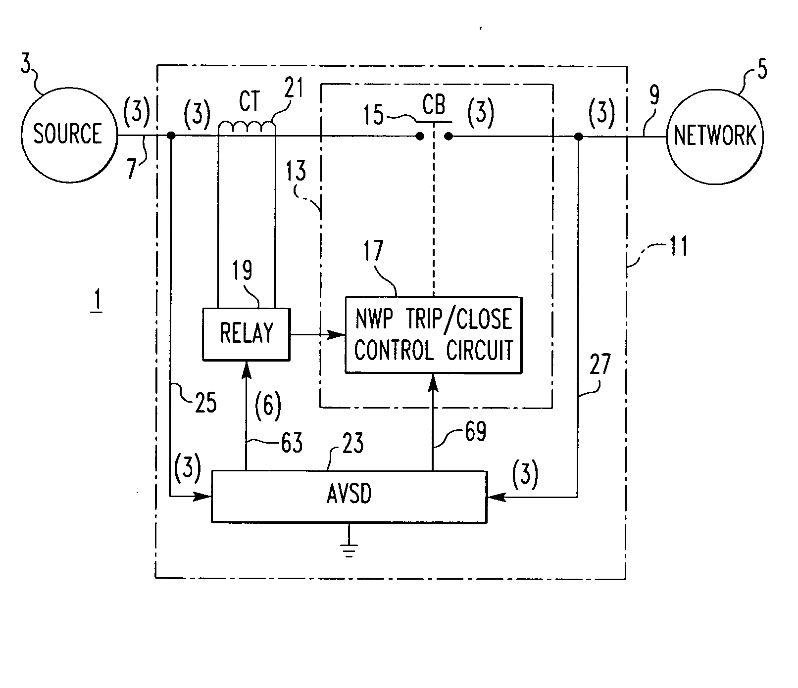
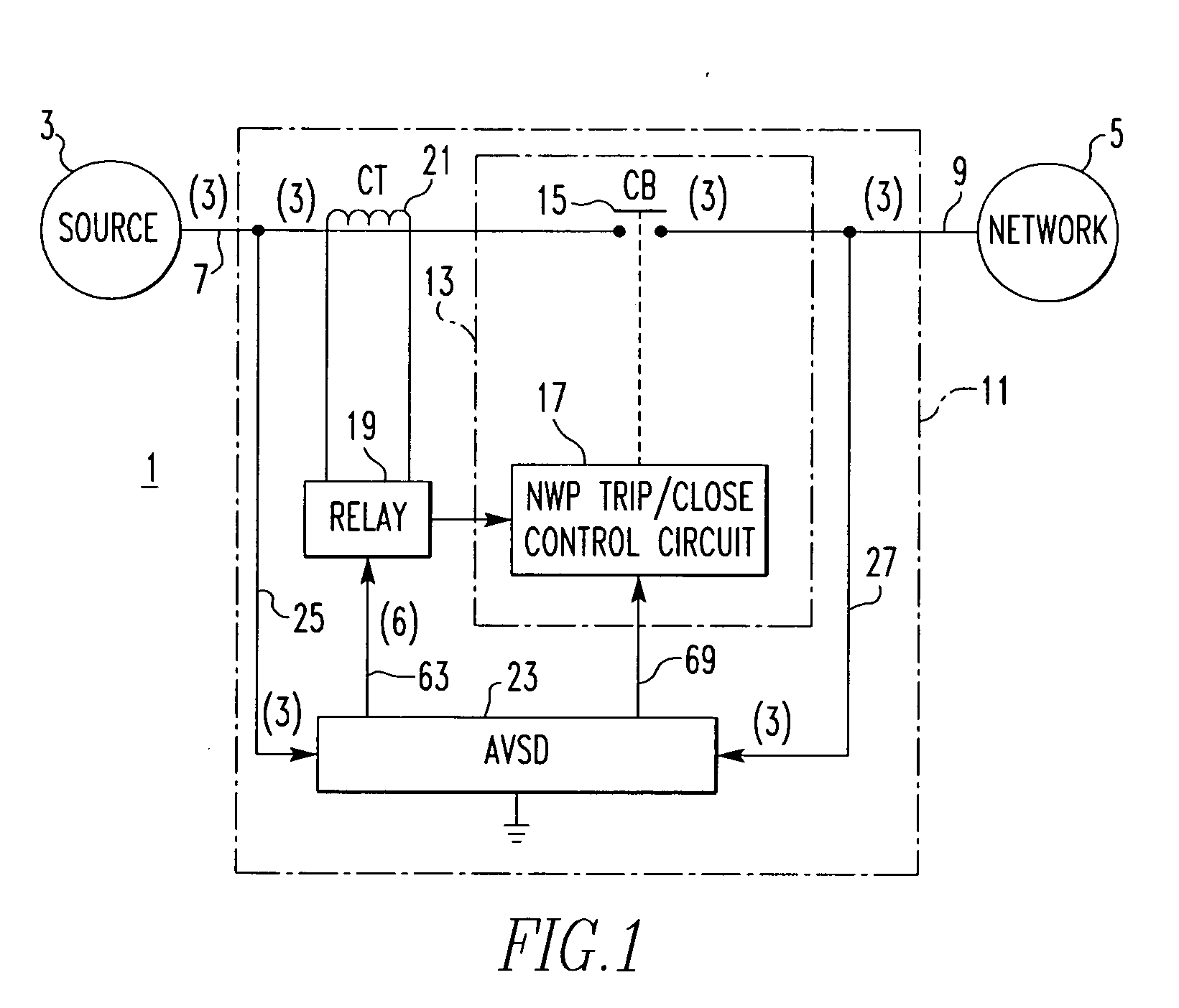
[0021]FIG. 1 illustrates schematically a portion of an electric power distribution system 1 in which a source 3 provides power to a network 5. The distribution system is three phase so that the source side and the network side each have three phase conductors 7 and 9, respectively, as indicated by the numerals “3” in parentheses adjacent the conductors in the single line drawing.

[0022] A network protector 11 connects the network 5 to the source 3 and provides protection for the network. This network protector 11 includes a circuit breaker 13 having separable contacts 15 connecting the source and network conductors 7 and 9 in each of the three phases. The separable contacts 15 are opened and closed by the network protector trip / close control circuit 17, which in turn is controlled by a network protector relay 19. Current transformers 21 sense the three phase currents passing through the separable contacts 15 for use by the control relay 19. If the relay 19 senses that current is flo...


PUM


Abstract

A voltage sensing device automatically scales the source and network phase voltages of a power distribution system having one of two operating voltages for input to a network protector relay and also automatically scales a voltage for operating the trip and close circuit of the circuit breaker in the network protector. A latching tap select relay only switches the system voltages to the lower operating voltage input taps of step down transformers after a short delay if all the system voltages are in the lower operating range. A diagnostic circuit verifies proper switch position and voltages before closing output contacts to connect the scaled voltages to the relay and circuit breaker.

Description

BACKGROUND OF THE INVENTION [0001] 1. Field of the Invention [0002] The invention relates to a network protector for use with power distribution systems having one of two generating voltages, and more particularly to a voltage device that in either case automatically scales the source and network phase voltages to the operating range of the network protector relay. [0003] 2. Background Information [0004] A low voltage secondary power distribution network consists of interlaced loops or grids supplied by two or more sources of power so that the loss of any one source will not result in an interruption of power. Such networks provide a high level of reliability, and hence, are widely used to supply power to high density load areas such as a section of a city, a large building, or an industrial site. [0005] Each source supplying power to the network is a medium voltage multi-phase feeder consisting of a multi-phase bus, a switch and a step down transformer. A network protector connects...

Claims


Application Information

Patent Timeline
IPC IPC(8): H02H11/00
CPCH02H11/007
Inventor FAULKNER, MARK A.ZIPAGAN, RONALD T.
Owner EATON INTELLIGENT POWER LIMITED
Learn More