Transmitting filter including saw resonators

a technology of transmission filter and saw resonator, which is applied in the direction of liquid surface applicators, coatings, chemical vapor deposition coatings, etc., to achieve the effect of lowering the applied power of the series arm and suppressing the deterioration and breakage of the series arm resonator

Inactive Publication Date: 2005-06-23
INTELLECTUAL VENTURES HOLDING 81 LLC
View PDF14 Cites 2 Cited by
  • Summary
  • Abstract
  • Description
  • Claims
  • Application Information

AI Technical Summary

Benefits of technology

[0011] In view of the aforementioned problem, the present invention may suppress the deterioration and break of the series-arm resonator of a surface acoustic wave filter by decreasing the current flowing in the series arm and thereby lowering the applied power to the series arm.

Problems solved by technology

It is known that these variation and break of the SAW branching filter characteristics are caused by deterioration and break of a series-arm resonator of the transmission filter to which a high power is applied.

Method used


Image

  • Transmitting filter including saw resonators
  • Transmitting filter including saw resonators
  • Transmitting filter including saw resonators

Examples


first embodiment

[0024] Next, the first embodiment will be described.

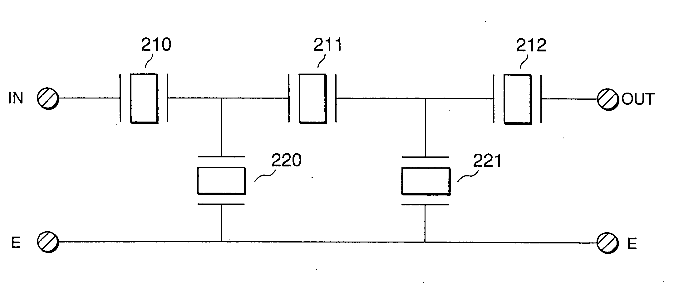
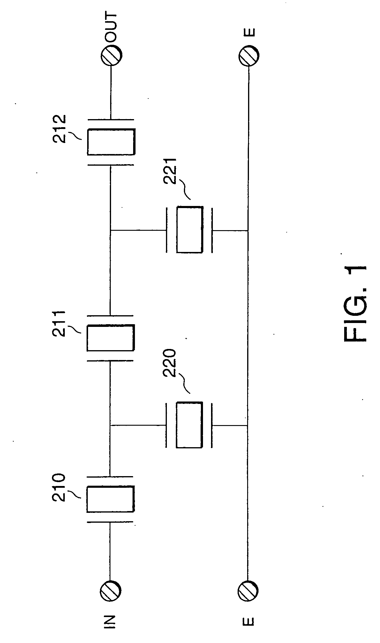
[0025]FIG. 1 is a circuit diagram of a Tx filter 200 of the first embodiment of the present invention.

[0026] In the terminal device for mobile communication, such as a portable telephone, illustrated in FIG. 6, in general, the output impedance ZPout at a PA terminal 103 as an output terminal of a power amplifier 180 is regulated to 50 Ω. It is known that the output power of this power amplifier 180 becomes, at the Tx terminal 101 of the SAW branching filter, from the relation between the input impedance ZTin at Tx and the output impedance ZPout of the power amplifier 180, a power input from the Tx terminal 101 of the SAW branching filter to a Tx filter 200 and a power reflected from the Tx terminal 101 of the SAW branching filter to the PA terminal 103 of the power amplifier 180.

[0027] In the terminal device for mobile communication, such as a portable telephone, the Tx filter 200 of FIG. 6 is a four-stage T-type ladder filter ma...

second embodiment

[0049] The circuit construction of the present invention is a polar construction.

[0050] In the aforementioned first embodiment, paying attention to the series arm 2 the applied power to which is the highest, the resonance frequency of the series arm 2 is changed and the resistance of the series arm 2 is reduced to lower the applied power to the series arm 2.

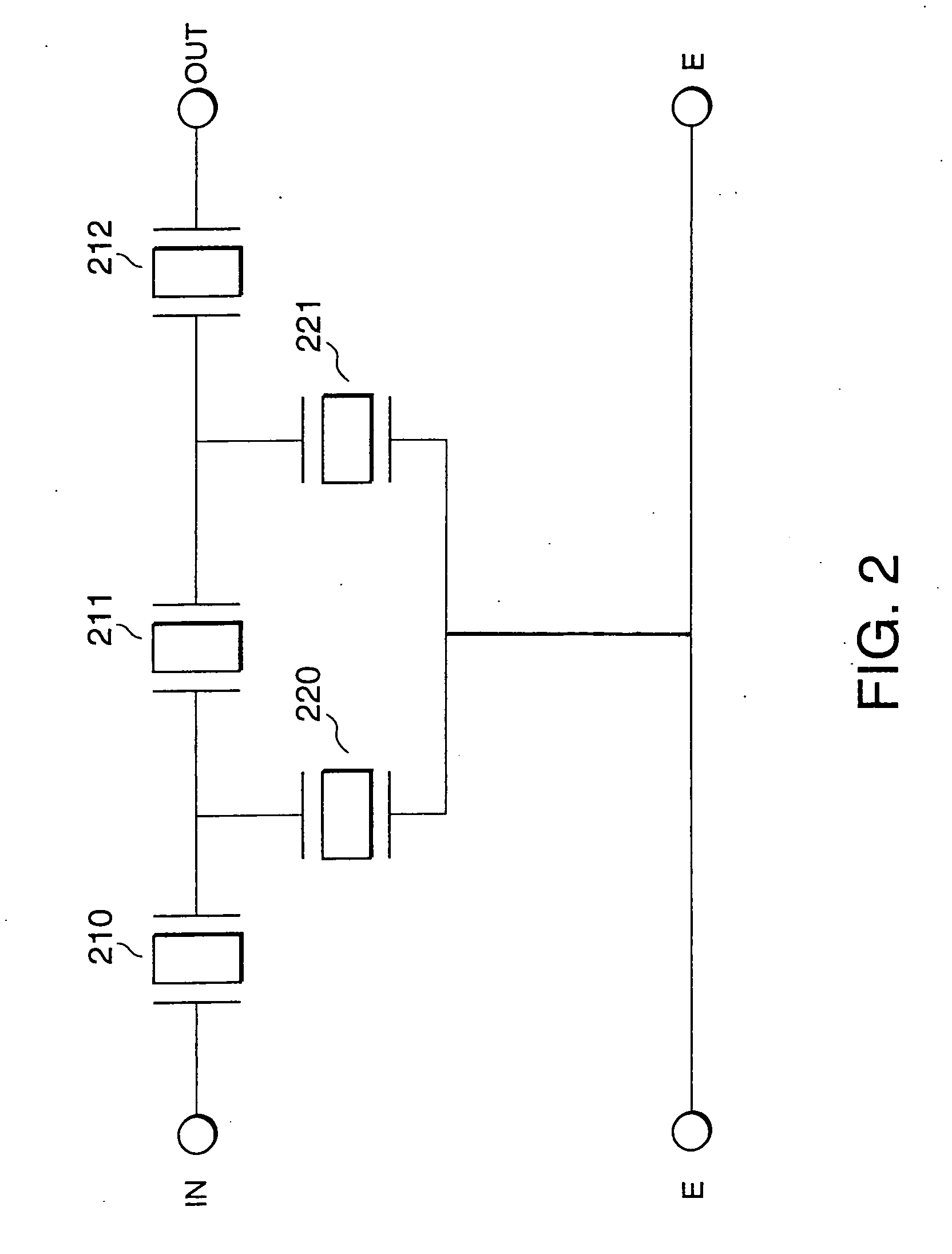
[0051] Contrastingly, this second embodiment is characterized in that, in the circuit of the Tx filter 200 of FIG. 2, the resistances of the parallel arms 1 and 2 are reduced and the current flowing through the series arm 2 is branched to the parallel arm 1 to lower the applied power to the series arm 2. As the means for reducing the resistances of the parallel arms, there are means for reducing the current value per unit area by enlarging the transverse length of teeth, means for also reducing the current value per unit area by increasing the number of pairs, and so on.

[0052] Table 6 shows the resistance value of each single p...


PUM

PropertyMeasurementUnit
impedanceaaaaaaaaaa
resonator frequencyaaaaaaaaaa
frequencyaaaaaaaaaa

Abstract

A surface acoustic wave filter includes an antenna terminal, a transmitting filter and a variable branching line both of which are coupled to the antenna terminal and a receiving filter coupled to the variable branching line. The transmitting filter has a first end series-arm SAW resonator, a second end series-arm SAW resonator, a middle series-arm SAW resonator coupled between the first and second end series-arm SAW resonators and parallel-arm SAW resonators. Each of the first and second end series-arm SAW resonator has a first resonance frequency. The middle series-arm SAW resonator has a second resonance frequency that is higher than the first resonance frequency.

Description

BACKGROUND OF THE INVENTION [0001] The present invention relates to surface acoustic wave branching filters comprising band-pass filters having ladder constructions with surface acoustic wave resonators, in small-size mobile communication instruments such as portable telephones, particularly to surface acoustic wave branching filters usable even in case of high applied powers. [0002] In recent years, developments of small-size, light mobile communication instruments such as portable telephones have been rapidly advanced. With this, reduction in size and improvement in performance of parts to be used have been pursued. To cope with this tendency, RF (Radio Frequency) parts using surface acoustic wave (hereinafter referred to as SAW) filters have been developed and used. In particular, SAW branching filters of FIG. 9 have been actively developed and part of them have been put in practical use and used because they are devices for largely contributing reduction in size of RF parts. [00...

Claims


Application Information

Patent Timeline
Patent Type & Authority Applications(United States)
IPC IPC(8): H03H9/72B05D3/06B05D7/24C23C16/44C23C16/455C23C16/48H03H9/64
CPCB05D1/60B05D3/061H03H9/6483C23C16/45591C23C16/482C23C16/45504
Inventor ANASAKO, KENICHIFUJITA, YOSHIAKIEHARA, HISANORIKOMAZAKI, TOMOKAZU
Owner INTELLECTUAL VENTURES HOLDING 81 LLC
Why Eureka
Try Eureka