
Cover for covering selected portions of a vehicle

a technology for selecting portions and vehicle covers, which is applied in the direction of vehicle components, superstructure subunits, roofs, etc., can solve the problems of foreign objects, expensive finishes of luxury vehicles, and sports cars, and is vulnerable to damage by the elements

Inactive Publication Date: 2005-06-23
BELL ERHARDT
View PDF48 Cites 2 Cited by
  • Summary
  • Abstract
  • Description
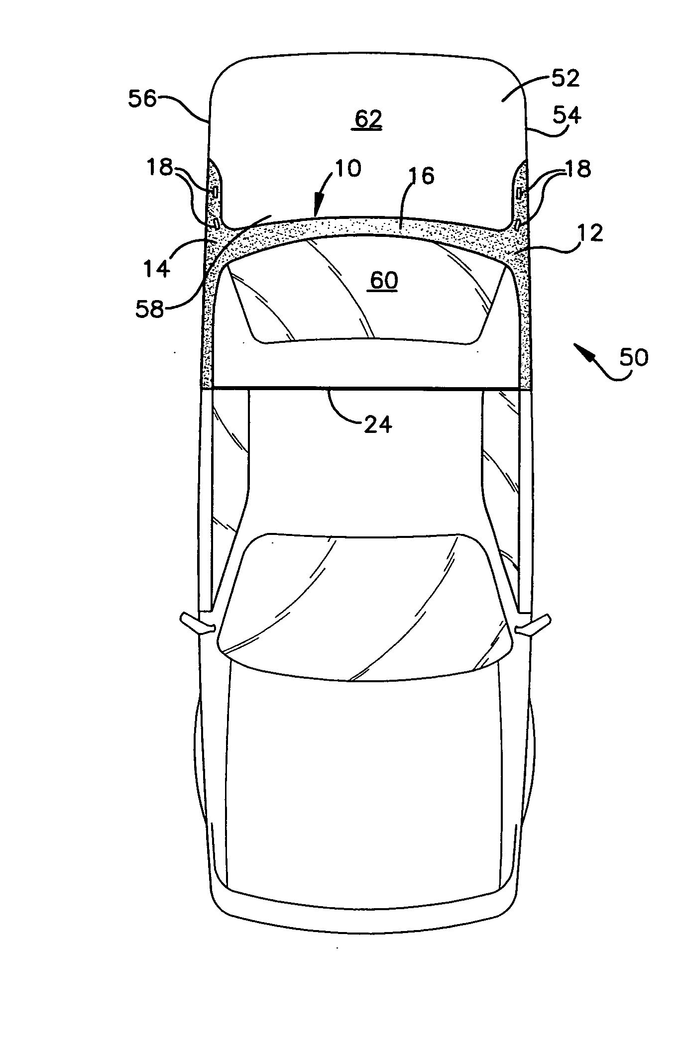
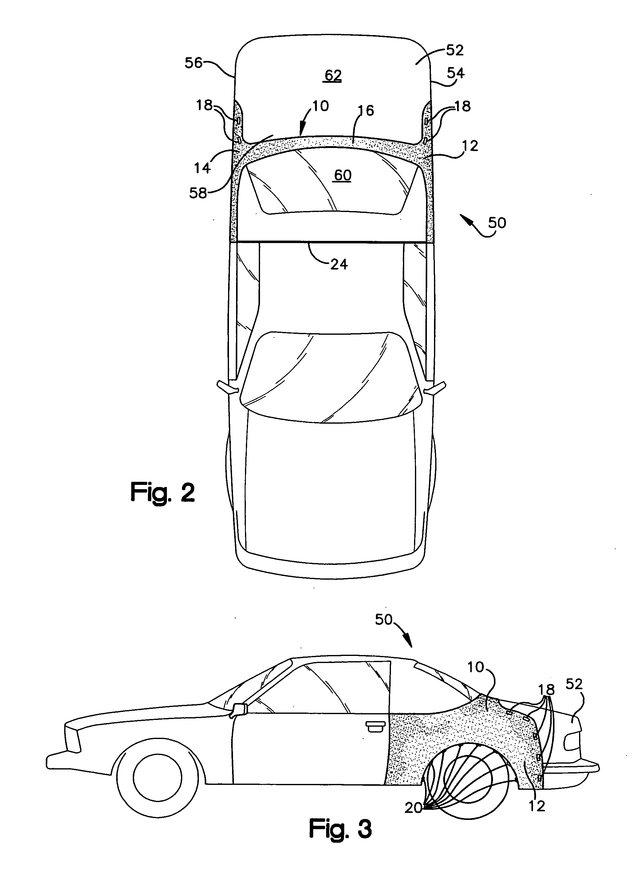
  • Claims
  • Application Information

AI Technical Summary

Benefits of technology

[0007] The present invention is directed to a decorative and functional vehicle covering. The covering is aesthetic in appearance so as not to detract from the overall appearance of the vehicle. The aesthetic appearance of the covering provides a vehicle with a distinctive appearance that tends to set one car apart from another and allows the owner to customize the vehicle. Also, the covering is functional in that it securely protects portions of the vehicle from damage by dirt and debris that may fall on or be thrown upon the rear fender.
[0008] In particular, the covering provides additional protection from paint damage on certain portions of the vehicle from paint or body damage caused by flying stones, chips and other airborne debris while driving. Furthermore, the covering has an attaching means that prevents theft of the covering and secures the covering to the vehicle while the vehicle is in operation. The covering is also designed for use on luxury vehicles, such as sports cars, so that the covering can protect the finish of the vehicle from damage and still not blow away when the car is operating at high speeds. Thus, when in position, the covering does not detract, and in fact enhances, the appearance of the car.
[0009] The present invention is directed to a cover for covering a portion of the rear of a vehicle. The cover can cover a least a portion of the rear fender on the driver and passenger side of the car. The cover also covers a portion of the rear top portion of the car. The cover protects those portions of the vehicle from paint or body damage while providing an attractive aesthetic appearance. The cover further includes attaching means, such as clamps and magnets that attach the cover to the vehicle to hold the cover in place. The cover further includes a strap that further attaches the cover to the vehicle.
[0011] A separate flexible or bunji-like strap connects the two leading edges of the cover that runs along the inside of the vehicle, providing absolute security against fly-off and further provides security against potential theft of the cover. A small extension of the cover has a section of the bra covering the inside door jam. A hole is cut out to fit over the door jam. On this section is the adjustable bunji-like cord strap that runs along the inside of the car, preferably behind the passenger seats.
[0012] Alternatively, a set of separate bunji-like straps (two straps) connect two leading edges of the cover located on the inside of the vehicle, providing absolute security against fly-off and further providing security against potential theft of the cover. A small extension of the cover has a section of the bra covering the inside door jam. A hole is cut out to fit over the door jam. On this section is a first strap that runs along the inside of the vehicle, preferably behind the passenger seats. The second strap cord is located several inches above the first strap serving the same purpose: pulling the car cover taught and into the interior of the car. This second strap runs parallel and along with the first strap.

Problems solved by technology

Moreover, the expensive finish of luxury vehicles, such as sports cars, are vulnerable to damage by the elements and foreign objects when driving, particularly at high speeds.

Method used


Image

  • Cover for covering selected portions of a vehicle
  • Cover for covering selected portions of a vehicle
  • Cover for covering selected portions of a vehicle

Examples


Embodiment Construction

[0021] Referring now to the figures, FIG. 1 shows a covering 10. The covering 10 may be made of leather, vinyl heat resistant plastic, or of any other known covering material. Covering 10 includes a first side flap 12 and a second side flap 14. A connecting strip 16 has two sides 17 and 15 and connects first and second side flaps 12 and 14 thereto. The connecting strip 16 further has a height h. First and second side flaps 12 and 14 extend from each side 15 and 17 of the connecting strip 16. The first and second side flaps 12 and 14 each have a width w that is greater than the height h of the connecting strip 16. Further, the first and second side flaps 12 and 14 each have a wheel well cutout portion 25 and 26 therein. Finally, first and second side flaps 12 and 14 include a means of attaching the covering 10 to a vehicle. Such means of attaching the covering 10 to a vehicle include magnets 18 and clamps or hooks 20 that are attached to the covering 10 and can be releasable connecte...


PUM


Abstract

A protective cover for a vehicle that extends over the rear fender and across the back portion and rear fender portions of a vehicle to protect the vehicle body from stones, mud, soil and debris. The cover consists of a thin layer of material and is designed to be attached onto the body using a series of clamps and / or magnets. The protective cover is designed for use while the vehicle is in motion. A series of magnets are attached along the leading, lower, and upper edges of the cover. The cover has a series of bendable clamps that are bent in such a manner as to provide a snug, adjustable fit depending on the car model. The strap or adjoining piece of material that runs across the back of the car connects the two main sections covering the fenders. A separate flexible strap connects the two leading edges of the cover that runs along the inside of the vehicle, providing absolute security against fly-off. At least one small extension of the cover has a section of the bra covering the inside door jam. The extension includes an opening to fit over the door jam. On this section is the flexible or adjustable strap that runs along the inside of the car, preferably behind the passenger seats. The cover may further include a second flexible strap adjacent to the first flexible strap.

Description

CROSS-REFERENCE TO RELATED APPLICATIONS [0001] This application claims priority from U.S. Provisional Patent Application Ser. No. 60 / 511,447 filed on Oct. 15, 2003, and from U.S. Provisional Patent Application Ser. No. 60 / 574,164 filed on May 25, 2004, which are hereby incorporated by reference.FIELD OF THE INVENTION [0002] The present invention is directed to a cover for covering a selected portion of a vehicle. In particular, the present invention is directed to a cover for a vehicle that extends over at least a part of the rear portion of a vehicle. BACKGROUND OF THE INVENTION [0003] Covers for selected parts of a motor vehicle have been previously utilized for portions including the front fender, hood, and bumper area including grill work and / or head lamps housing. These covers are commonly referred to as “masks” or “bras.” Such covers include one-piece and two-piece covers for covering some or all of the above mentioned areas. Traditionally, such front-end covers are made of le...

Claims


Application Information

Patent Timeline
Patent Type & Authority Applications(United States)
IPC IPC(8): B60J7/20B60J11/00
CPCB60J11/06
Inventor BELL, ERHARDT
Owner BELL ERHARDT
Learn More