
Solar generator panel and an associated satellite

Inactive Publication Date: 2005-06-23
THALES SA
View PDF6 Cites 37 Cited by
  • Summary
  • Abstract
  • Description
  • Claims
  • Application Information

AI Technical Summary

Benefits of technology

[0015] An object of the invention is thus to provide a solar generator panel comprising a plane array of strings of solar cells and which solves the above-mentioned drawbacks by making it possible to reduce the area lost for connections between the satellite and the terminals of the strings, and also making it possible to reduce the risks of voltage differences between adjacent cells.

Problems solved by technology

Naturally, this excellent result comes from the small number of strings per panel, which is a characteristic of strings of silicon cells, leading to only a small area being lost.
Nevertheless, several drawbacks arise when it comes to using GaAs cells: firstly, it is necessary to find a solution to connecting the positive and negative terminals of the strings of cells, which solution must be capable of optimizing the space occupied by the terminals; secondly, it is known that if the voltage between adjacent cells is above a certain threshold, then the working current from the string can flow between two cells via a plasma created by a primary electrostatic discharge.
This process of pyrolysis leads to a permanent short circuit between the two cells, and thus between two rows of adjacent cells, which leads to permanent destruction of a portion of the solar generator, which then becomes incapable of delivering all of its working power to the equipment of the satellite.
As a result of the small distance between the cells (or the terminals) associated with a high potential difference, there is a risk of an electric arc appearing, as explained above.
Nevertheless, the spacing created in this way leads to a reduction in the cell occupancy ratio of the panel, thereby decreasing the solar energy power that the panel can collect.

Method used


Image

  • Solar generator panel and an associated satellite
  • Solar generator panel and an associated satellite
  • Solar generator panel and an associated satellite

Examples


Embodiment Construction

[0027] Below, elements performing functions that are identical or similar are given the same references.

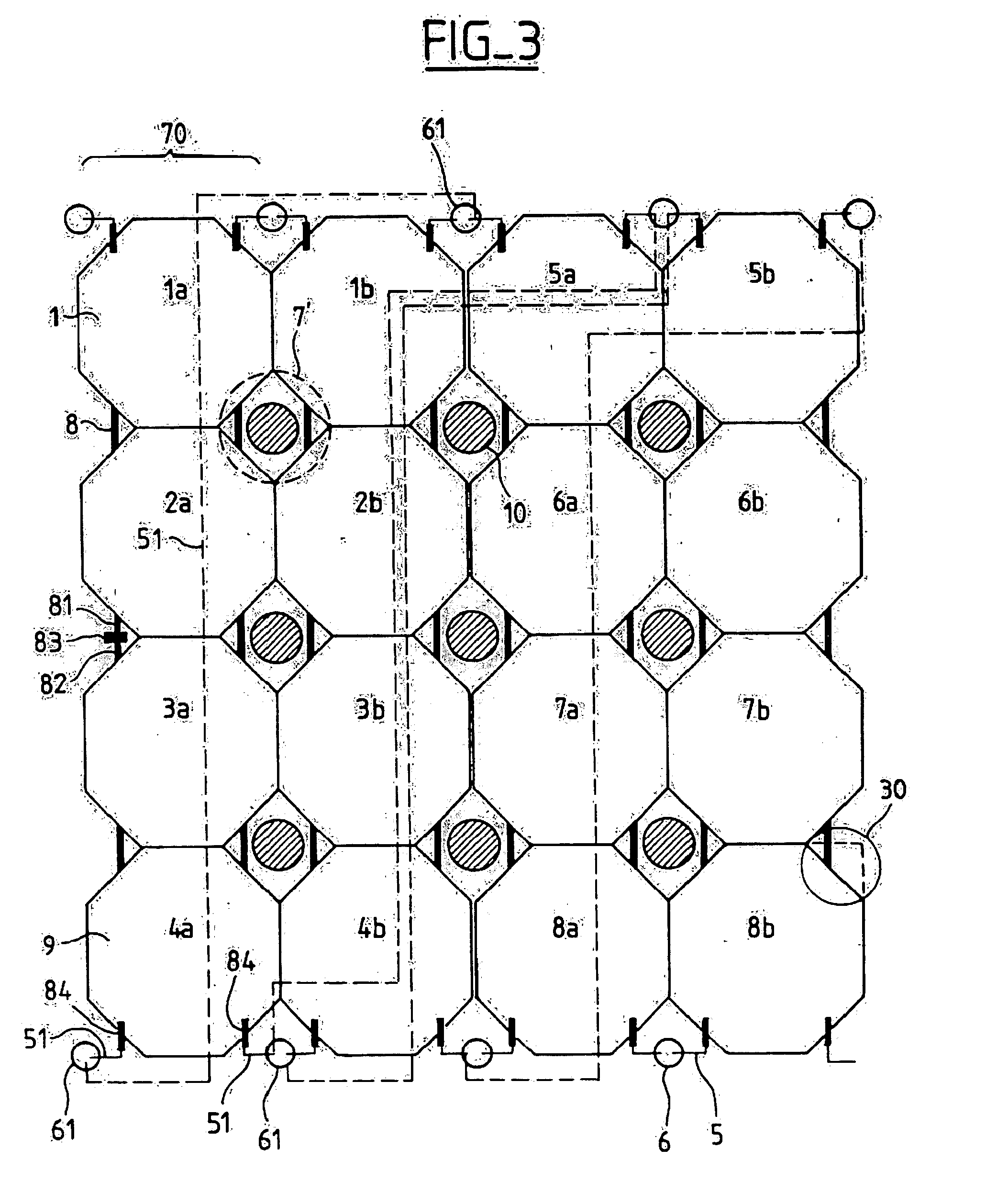
[0028]FIG. 3 is a diagram of a plane array 100 of octagonal cells in a first embodiment of the invention.

[0029] For better clarity when distinguishing the various strings of cells, only two strings of cells are shown, the first comprising cells referenced 1a to 8a, and the second comprising cells referenced 1b to 8b.

[0030] The order in which they are numbered corresponds to the order in which electrical continuity is implemented. Thus, two successive cells in a given string are interconnected by a connection 8. In fact, this connection is made up of two sub-connections 81 and 82, each being secured to one of the two successive cells, and the two sub-connections being bonded to each other at a junction point 83.

[0031] The junction point 83 is shown in FIG. 3 with the two sub-connections 81 and 82 being equivalent in length. Nevertheless, in a preferred variant, the cells are as...


PUM


Abstract

A solar generator panel comprising a plane array of strings of photovoltaic cells disposed side by side. According to the invention, the cells have cropped corners suitable for generating free spaces in the interstices between the cropped corners. It is then possible to place openings in those spaces for passing cables and / or for receiving damper blocks. The invention is particularly applicable to solar panels for satellites.

Description

BACKGROUND OF THE INVENTION [0001] The present invention relates in general manner to the field of solar energy generator panels, in particular for space applications. More particularly, it relates to a solar generator panel comprising an array of strings of photovoltaic cells disposed side by side and forming a substantially rectangular grid. [0002] The solar generator panels transported in a space vehicle such as a satellite generally comprise: [0003] an array of solar cells formed by strings of cells electrically connected to the satellite, the array covering the surface of support panels and serving to transform solar energy into electrical energy; and [0004] said support panels supporting the arrays of cells comprising a substrate. [0005] Such solar generator panels can be distributed in a wide variety of configurations. Conventionally, they comprise a longitudinal succession extending parallel to a direction going away from the body of the space vehicle, and around which the g...

Claims


Application Information

Patent Timeline
IPC IPC(8): B64G1/44H01L31/042H01L31/05H02S30/20
CPCB64G1/443H01L31/042Y02E10/50H01L31/0504H01L31/0201H01L31/02013H01L31/035281H01L31/045
Inventor BOULANGER, BERNARDDELCLOS, HUBERT
Owner THALES SA
Learn More