
Replacement ligamentum teres femoris

Inactive Publication Date: 2005-06-16
MOR AMIT
View PDF27 Cites 3 Cited by
  • Summary
  • Abstract
  • Description
  • Claims
  • Application Information

AI Technical Summary

Benefits of technology

[0010] The neuromuscular control system of the body integrates peripheral sensations relative to joint loads and processes these signals into coordinated motor responses. This muscle activity serves to protect joint structures from excessive strain.

Problems solved by technology

No known hip joint prostheses have or are connected to a ligamentum teres, perhaps because of the prevalent belief that “the ligament does not contribute to the integrity of the joint or control movements there”.

Method used


Image

  • Replacement ligamentum teres femoris
  • Replacement ligamentum teres femoris
  • Replacement ligamentum teres femoris

Examples


Embodiment Construction

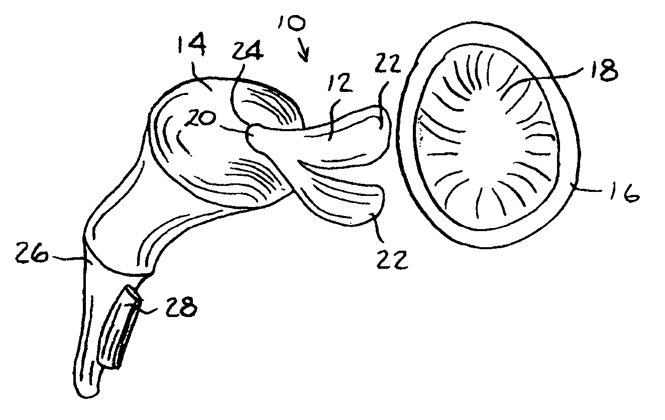
[0025] Reference is now made to FIG. 4, which illustrates a hip joint prosthesis 10, constructed and operative in accordance with an embodiment of the present invention.

[0026] The prosthesis 10 may comprise a replacement ligamentum teres femoris 12, which may be attached to a replacement femoral head 14. Alternatively, replacement ligamentum teres femoris 12 may be attached to a natural femoral head. The replacement ligamentum teres femoris 12 may be stretchable and may be constructed of any suitable medically-safe elastomer, such as but not limited to, polyurethane, polyurethane bionate, silicone and the like, or may be obtained or made from a natural ligament or other natural tissue or substance (e.g., some other ligamentum teres femoris and the like). The properties of the elastomer may be selected or engineered to mimic the properties of a natural ligamentum teres femoris.

[0027] The replacement ligamentum teres femoris 12 may be of any shape or size, such as but not limited to...


PUM


Abstract

A hip joint prosthesis including a replacement ligamentum teres femoris. The replacement ligamentum teres femoris may be attached to a replacement (or natural) femoral head and / or to a replacement (or natural) acetabular structure.

Description

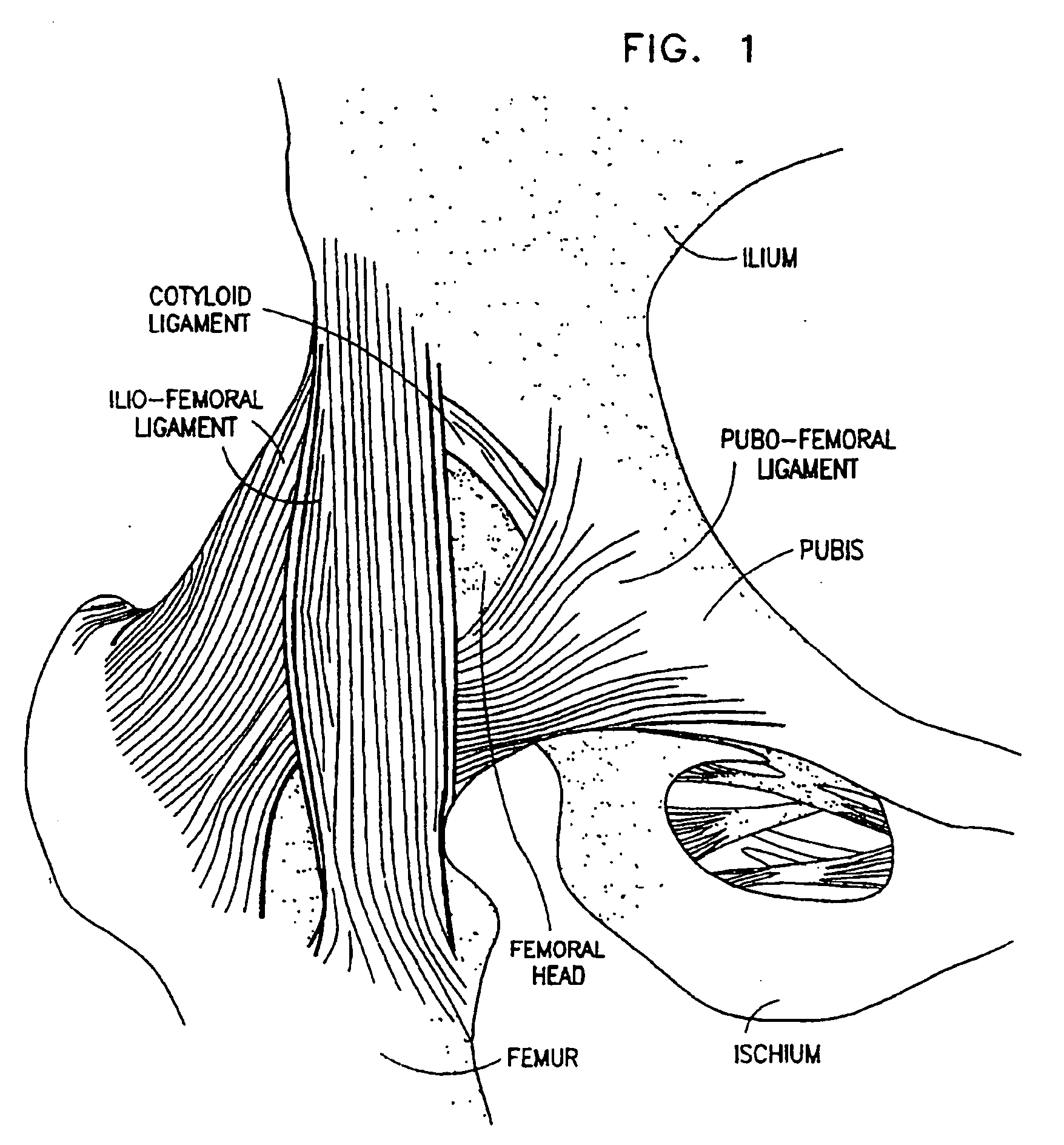
FIELD OF THE INVENTION [0001] The present invention relates generally to an enarthrodial prosthesis, and particularly to a replacement ligamentum teres femoris for a hip joint prosthesis. BACKGROUND OF THE INVENTION [0002] The hip joint (whose scientific name is the coxal articulation) is an enarthrosis (ball-and-socket joint). Many kinds of hip joint prostheses are known. For a better understanding of a hip joint prosthesis, a basic description of the human hip joint is presented here with reference to FIGS. 1-3. [0003] The femoral head (head of the thigh bone) articulates with the acetabulum of the innominate bone, known in non-technical terms as the socket of the hipbone. The innominate bone in the area of the hip joint is made of three portions: the upper portion is called the ilium, the middle portion is called the pubis and the lower portion is called the ischium. The femoral head is connected to the innominate bone by a plurality of ligaments. The ligaments shown in FIG. 1 ar...

Claims


Application Information

Patent Timeline
IPC IPC(8): A61B17/00A61B17/06A61F2/00A61F2/08A61F2/32A61F2/34A61F2/36
CPCA61B17/00491A61B17/06166A61F2/08A61F2/32A61F2/34A61F2002/3668A61F2/3662A61F2002/30069A61F2002/3611A61F2002/3625A61F2/36A61F2002/30884
Inventor MOR, AMIT
Owner MOR AMIT
Learn More