
Stretching device

Inactive Publication Date: 2005-06-16
INNOVATIVE BIOMECHANICAL SOLUTIONS L L C
View PDF39 Cites 7 Cited by
  • Summary
  • Abstract
  • Description
  • Claims
  • Application Information

AI Technical Summary

Benefits of technology

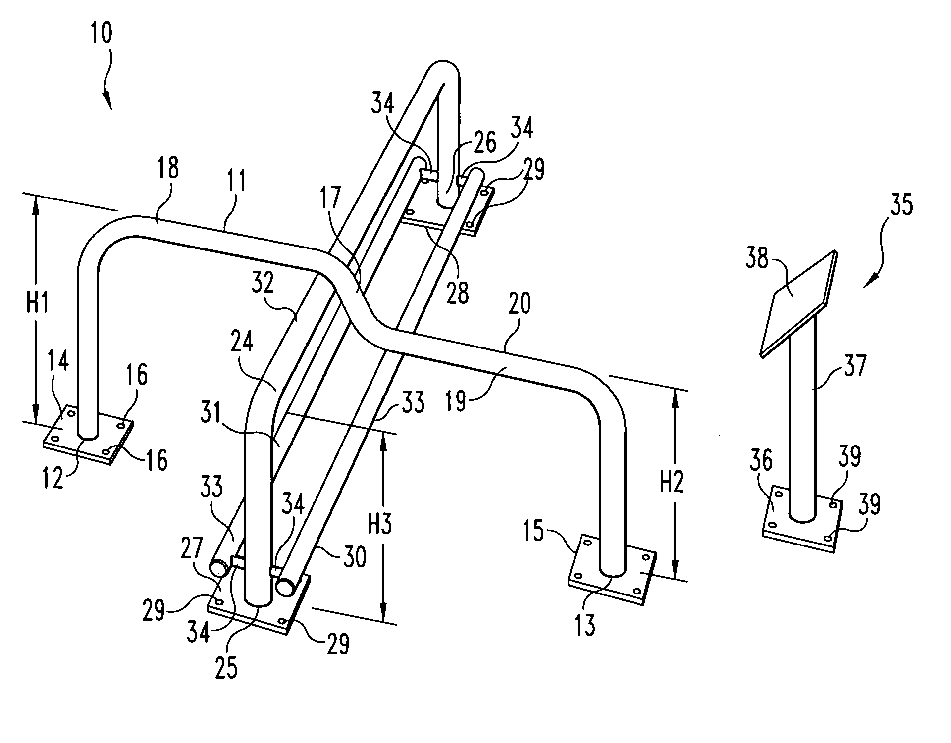
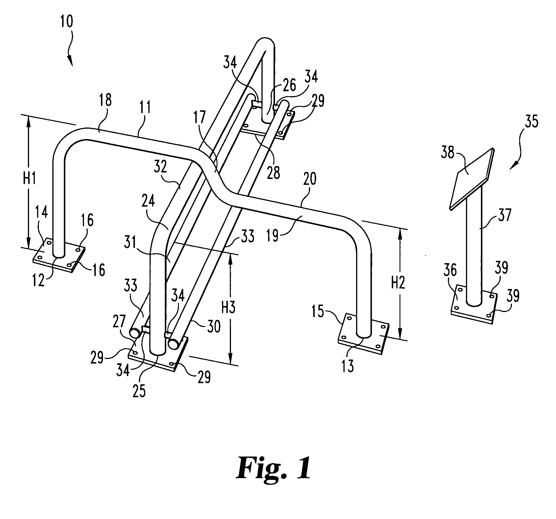
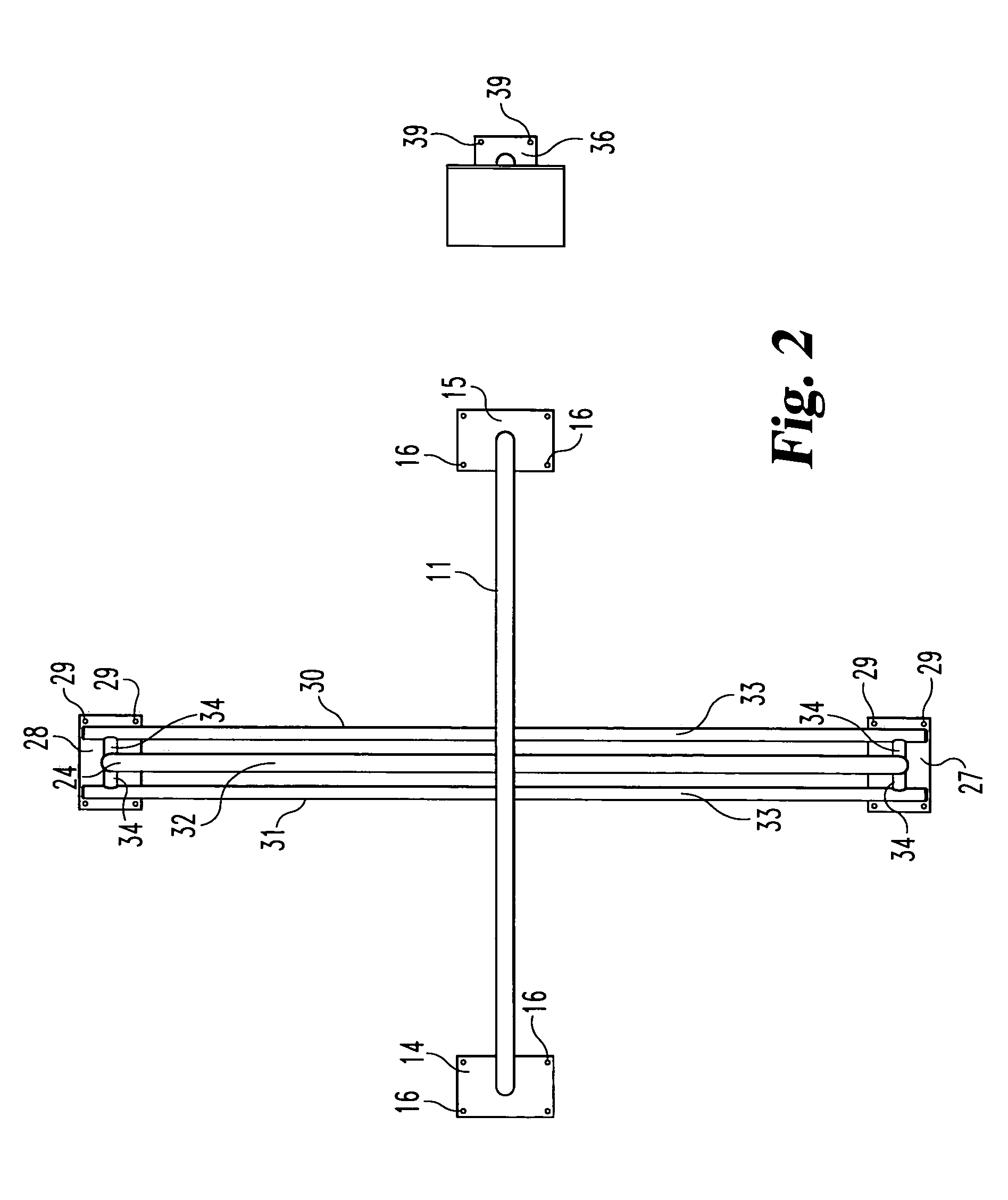
[0006] A device may be used to facilitate stretching before engaging in athletic activities. The device may have two inverted U-shaped members affixed to the ground at the ends of each member. One U-shaped member may be affixed to the ground at its ends in a generally transverse orientation to the other U-shaped member. One U-shaped member may be between about 44 to 30 inches in height from the ground and between about 1 to 6 inches in width. An instructional sign may also be included with stretching instructions thereon. The device facilitates stretching.

Problems solved by technology

Failure to stretch the leg, hip, and lower back muscles before playing sports, such as playing a round of golf, can lead to decrease in performance while playing a round.
Muscle strain and injury may be an even greater danger caused by failing to stretch the muscles before playing.
Most existing stretching devices are more suited for a younger athletic user, whereas many golfers may be elderly, or unfit or even handicapped.
Moreover, even if a golfer remembers to stretch, few understand the proper stretching exercises to be performed before a round a golf.

Method used


Image

  • Stretching device
  • Stretching device
  • Stretching device

Examples


second embodiment

[0024] Referring now to FIG. 6, the invention is shown. First U-shaped member 46 has a first end 47 and a second end 48. It also has a first mounting plate 49 and a second mounting plate 50. Both mounting plates include clearance holes 51. First U-shaped member has a horizontal section 52 having a top surface 53. As is readily apparent from FIG. 6, the length of the horizontal section of U-shaped member 46 may be substantially shorter than the length of the corresponding horizontal section depicted in FIG. 1. In addition, the first U-shaped member 46 may differ from the U-shaped member 11 depicted in FIG. 1 in the fact that there is ordinarily no downwardly sloping section along the middle. The second U-shaped member 55 runs transverse to first U-shaped member 46 generally along the middle of both first U-shaped member 46 and second U-shaped member 55, although it could also run at any non-perpendicular angle, if so desired. The height of second U-shaped member 55 may be less than t...

third embodiment

[0026] Referring now to FIG. 7, the invention is shown. This embodiment is identical to the embodiment disclosed in FIG. 1 except for the method of attaching first elongated member 30 and second elongated member 31. The alternative mounting plates 45 disclosed in FIG. 5 provide a surface to integrate elongated member 30 and 31 into second U-shaped member 24. Elongated members 30 and 31 may be affixed to the alternative mounting plates 45 through any reasonable means such as welding, brazing, using fasteners, or any other means known to one skilled in the art that would provide permanent and affixed attachment.


PUM


Abstract

A device to facilitate stretching before engaging in athletic activities, particularly golf, is disclosed. Two inverted U-shaped members are permanently affixed to the ground using mounting plates or any other potential means. One of the U-shaped members runs underneath the other in a transverse direction generally along the center of each member. The top surfaces of the U-shaped members are designed to provide three differing levels of height thereby allowing a variety of stretches to be performed by the user. An informational sign depicting a variety of stretches may be included. One or multiple users may use this device to help facilitate a variety of stretches to improve flexibility.

Description

TECHNICAL FIELD [0001] The invention relates to stretching, and more particularly to a device and method to facilitate stretching before engaging in athletic activities such as, for example, golf BACKGROUND OF INVENTION [0002] Sports are enjoyed by millions of people worldwide. Failure to stretch the leg, hip, and lower back muscles before playing sports, such as playing a round of golf, can lead to decrease in performance while playing a round. Muscle strain and injury may be an even greater danger caused by failing to stretch the muscles before playing. [0003] Stretching devices have been well known in the art for many years. Many devices are intended to be taken and used at home or to be portable. In addition, many devices are intended to facilitate only one type of stretch instead of a number of different stretches. Most existing stretching devices are more suited for a younger athletic user, whereas many golfers may be elderly, or unfit or even handicapped. The stretching devic...

Claims


Application Information

Patent Timeline
IPC IPC(8): A63BA63B9/00A63B17/00A63B23/00A63B26/00
CPCA63B21/00047Y10S482/907A63B2023/006
Inventor PHIPPS, PAUL
Owner INNOVATIVE BIOMECHANICAL SOLUTIONS L L C
Learn More