
Conveyor for printed sheet material with air assisted drop

Inactive Publication Date: 2005-06-16
GOSS INT AMERICAS
View PDF19 Cites 0 Cited by
  • Summary
  • Abstract
  • Description
  • Claims
  • Application Information

AI Technical Summary

Benefits of technology

[0006] An object of the present invention is to provide a pocket conveyor providing reduced friction during a drop. An alternate or additional object of the present invention is to provide a pocket conveyor which can improve transfer of printed sheet material.

Problems solved by technology

Parts of the collected printed sheet material, when dropped from the pocket, may encounter friction against parts of the pocket and thus fall unevenly or become stuck in the pocket.
This can cause problems with spine registration or with further conveying of the printed sheet material.
Spine registration is adversely impacted, and malfunction of the entire device may result.

Method used


Image

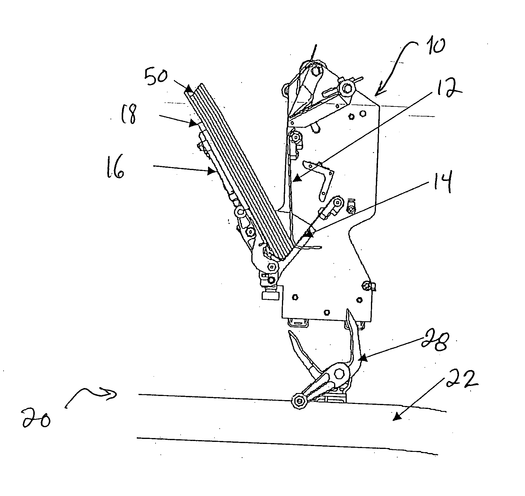
  • Conveyor for printed sheet material with air assisted drop
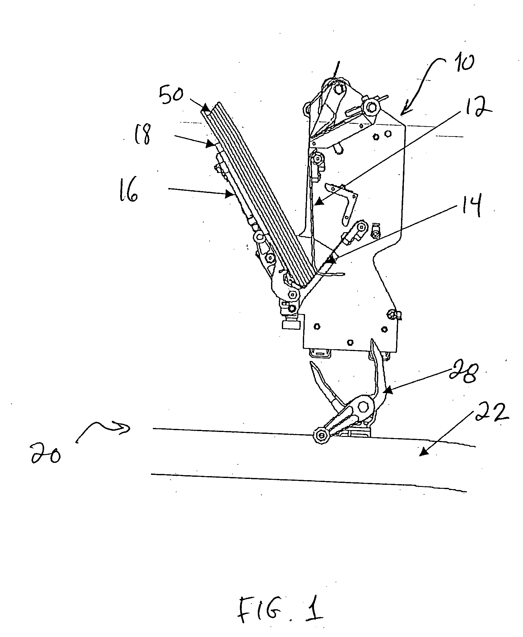
  • Conveyor for printed sheet material with air assisted drop
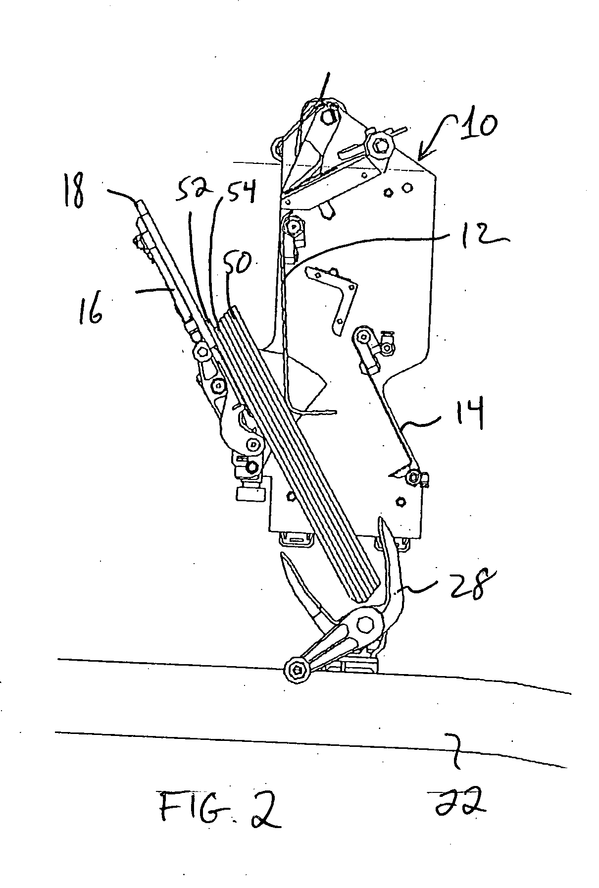
  • Conveyor for printed sheet material with air assisted drop

Examples


Embodiment Construction

[0022]FIG. 1 shows a moving pocket 10 above a gripper conveyor 20 with grippers 28 moving along a track 22. Pocket 10 may have a collect wall 18, and a foot 14. Printed sheet material 50 is collected, for example by collation, so as to be supported by foot 14 and so as to rest against collect wall 18. Collect wall 18 is angled with respect to the pocket travel direction and may be moveable or adjustable. Attached to collect wall 18 is an air manifold 16 for supplying low pressure air through air holes in collect wall 18 when the air manifold 16 is supplied with pressurized air.

[0023] As shown in FIG. 5, air holes 30 may be spaced across the width and height of collect wall 18, and the further apart holes in each direction preferably extending at least half the width of the printed material so as to be able to create a substantial air cushion between the wall 18 and printed sheet material 50.

[0024] Pocket 10, as shown in FIG. 1, may also further include a spring wall 12 which maint...


PUM

PropertyMeasurementUnit
Pressureaaaaaaaaaa
Areaaaaaaaaaaa
Frictionaaaaaaaaaa

Abstract

A sheet material conveyor includes a pocket conveyor with at least one moving pocket for collecting printed sheet material, the pocket conveyor having a release area for releasing the printing sheet material in the pocket. The sheet material conveyor also includes an air supply device providing air to the pocket at the release area. A pocket with air supply holes and a method for releasing printed sheet material using pressurized air is also provided.

Description

BACKGROUND INFORMATION [0001] The present invention relates generally to the graphic arts industry and more particularly to a conveyor for printed sheet material, as well as to a method for transferring printed sheet material. [0002] After printing by a printing press, printed sheet material may be cut, folded and collected into stacks. Newspaper sections for example may be collected together. The collected sheet material is then transferred and conveyed in various manners. The collected sheet material may be for example collected in individual moving pockets. The collected sheet material may be collected by insertion into open sections, or by collation as separate individual sheets or sections are placed side-by-side, or by both insertion and collation. [0003] An example of a pocket conveyor is for example found in U.S. Pat. No. 6,447,229, which prepares spines for binding, which is hereby incorporated by reference herein. U.S. Pat. Nos. 4,479,643 and 3,874,649 also disclose pocket...

Claims


Application Information

Patent Timeline
IPC IPC(8): B65H39/02
CPCB65H39/02B65H2301/42242B65H2301/4321B65H2301/44712B65H2220/01
Inventor CARON, GLEN ROGERGUARALDI, GLENN ALANMEYER, RICHARD CRAIG
Owner GOSS INT AMERICAS
Learn More