
Applicator and method for in-mold coating

a technology of in-mold coating and nozzle, which is applied in the direction of liquid surface applicators, coatings, other domestic articles, etc., can solve the problems of operators coating the uncoated parts, difficult-to-reach areas of mold, and difficult-to-reach areas of undercut mold portions 20

Inactive Publication Date: 2005-06-16
LEAR CORP
View PDF26 Cites 8 Cited by
  • Summary
  • Abstract
  • Description
  • Claims
  • Application Information

AI Technical Summary

Benefits of technology

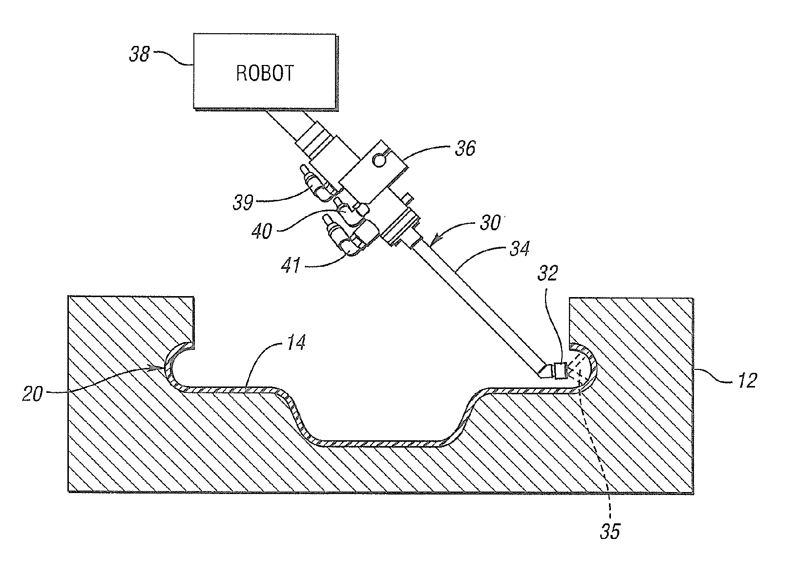
The present invention provides an improved applicator and method for coating difficult-to-reach in-mold portions of a mold cavity in one coating operation and without requiring excessive amounts of coating. The applicator has a spray head and body portion at an oblique angle to each other, which enhances the spraying of the coating onto the difficult-to-reach surfaces of the mold. The applicator also includes a liquid medium head and a closable and operable liquid medium valve for selectively controlling a sufficient flow of liquid medium for atomization with the delivered gaseous medium. The method includes spraying a first atomized fluid onto the mold including the undercut surfaces from an applicator having a body portion and a spray head extending at an oblique angle with respect to the body portion. The spray head is positional within the mold in a head-on position sufficient to squarely spray the atomized fluid onto the mold and the first undercut surface.

Problems solved by technology

The undercut mold portion 20 is a difficult-to-reach area for applying the coating.
Thus, such areas are considered difficult-to-reach areas of mold 12.
It is expensive, however, to have operators coat the uncoated portions in a secondary operation, and it is similarly expensive to apply excess material to the mold.
Moreover, the excess coating can cause additional problems in bi-color applications in which it is desirable to have one portion of the skin coated with a first color and another portion of the skin coated with a second different color, as the running of coating material from one color into the other color can discolor the appearance of the skin.

Method used


Image

  • Applicator and method for in-mold coating
  • Applicator and method for in-mold coating
  • Applicator and method for in-mold coating

Examples


Embodiment Construction

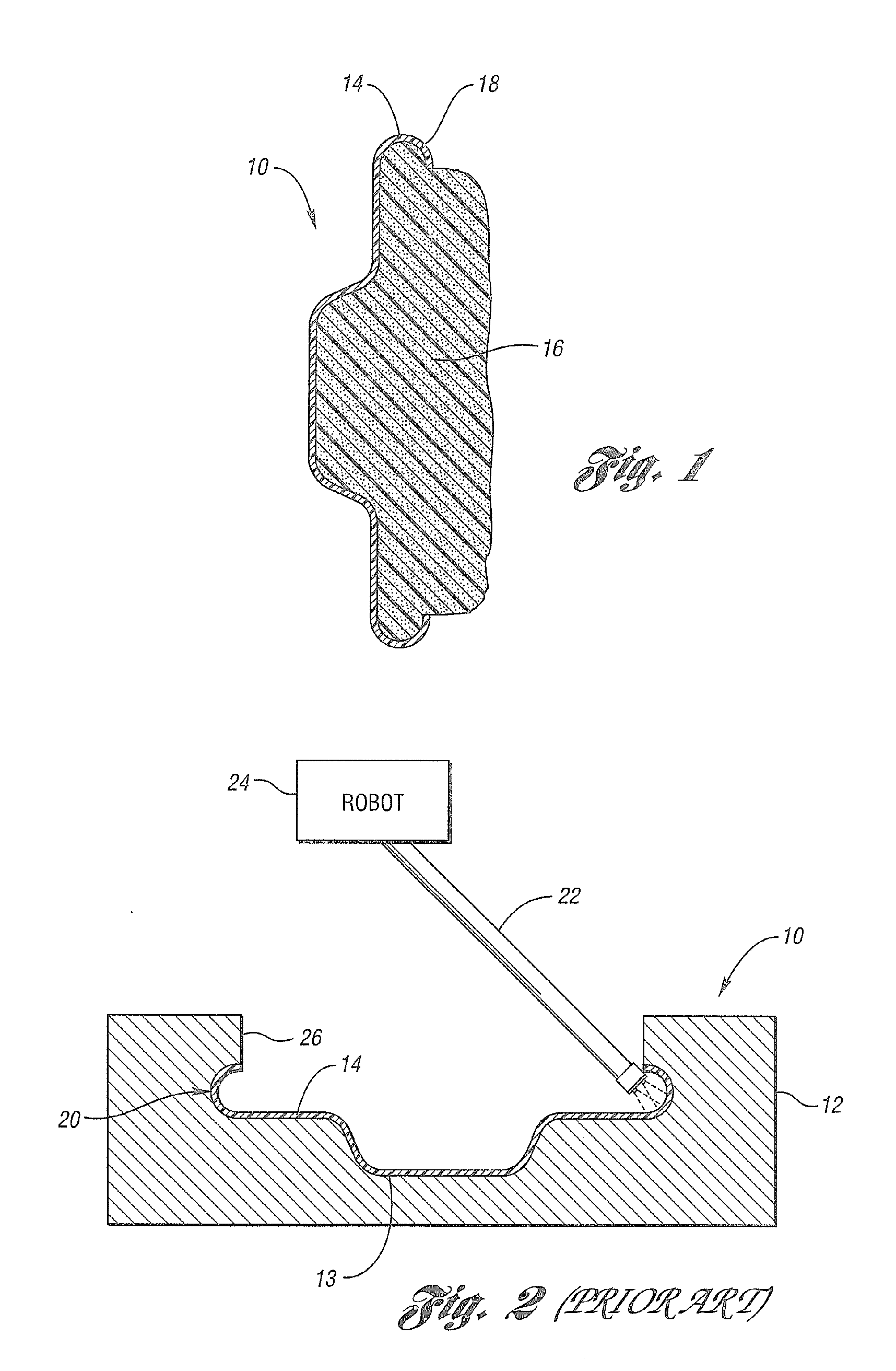
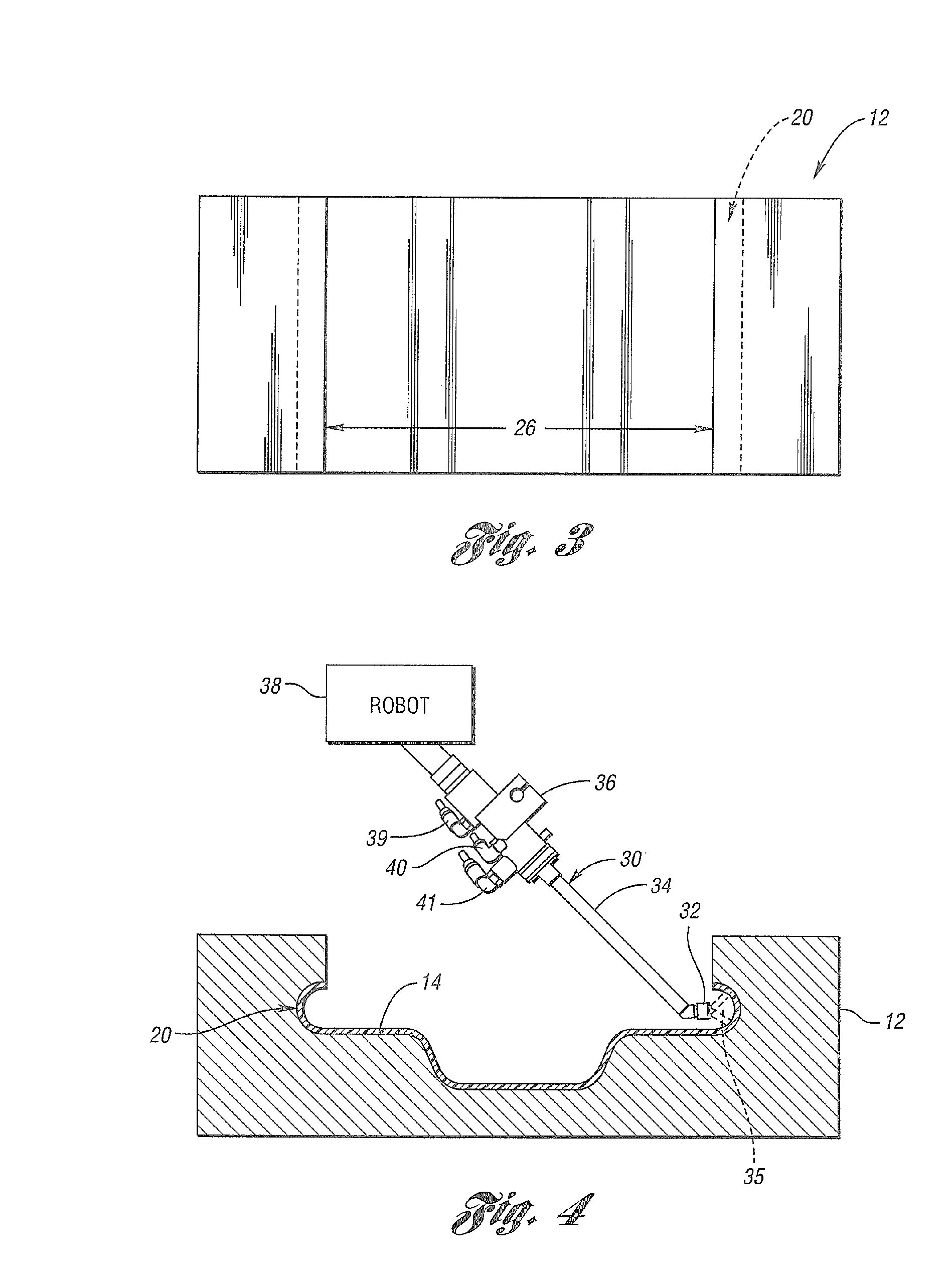
[0023]FIG. 4 shows an improved applicator device or applicator, according to the invention, for applying a coating to mold 12. The applicator of the invention is hereinafter referred to with reference numeral 30, and can be used in any number of applications in which it is desirable to spray a coating onto a mold. One area of interest is in processes used to manufacture soft interior components for automotive vehicles, like the skin making process and foam-in-the-mold process used to manufacture instrument panel 10 shown in cross-section in FIG. 1. As described above, instrument panel 10 can be manufactured by spraying mold 12 with a coating such as polyurethane, polyvinylchloride, or other material to form a relatively thin covering type skin 14 that forms a covering panel for covering a soft foam material 16.

[0024] In either the skin making process or the foam-in-the-mold process, the applicator 30 may deliver either waterborne or solvent-borne, one component or two component, co...


PUM

PropertyMeasurementUnit
distanceaaaaaaaaaa
distanceaaaaaaaaaa
diameteraaaaaaaaaa

Abstract

An in-mold applicator and method for spraying a coating on difficult-to-reach surfaces of a mold is disclosed. The applicator includes a spray head and a base portion at an oblique angle to each other. The outer dimensions of the body portion and the spray head are sufficiently small so that taken in combination with the oblique angle, the applicator and method can enhance the spraying of the coating to difficult-to-reach surfaces within the mold.

Description

CROSS-REFERENCE TO RELATED APPLICATION [0001] This application is a divisional of U.S. application Ser. No. 10 / 115,360, filed Apr. 3, 2002 and entitled “Applicator and Method for In-Mold Coating.”BACKGROUND OF THE INVENTION [0002] 1. Field of the Invention [0003] The present invention relates to an improved nozzle for use with in-mold coating processes. [0004] 2. Background Art [0005] In-mold coating processes are used in a number of applications to spray, or otherwise apply, coatings onto the working surfaces of molds used in molding operations. One common application of in-mold coating can be found in the processes used for manufacturing the soft interior paneling of automotive vehicles, like the soft interior paneling of an instrument panel dashboard 10, shown in cross-section in FIG. 1. Instrument panel 10 can be manufactured by a skin making process or a foam-in-the-mold process that each include spraying a mold, like mold 12 shown in FIG. 2, with a coating such as a one or two...

Claims


Application Information

Patent Timeline
Patent Type & Authority Applications(United States)
IPC IPC(8): B05B7/08B05B7/12B29C31/04B29C37/00
CPCB05B7/0815B05B7/0861B05B7/1254B29L2031/3008B29C37/0032B29K2075/00B29C31/045B05B7/1272
Inventor DONATTI, JOSEPH T.MELLENTINE, ANDREW P.WILLIAMS, GLENN D.
Owner LEAR CORP
Learn More