Sealed electron beam source

a technology of electron beam and electron beam, which is applied in the field of x-ray systems, can solve the problems of high-voltage instability, new constraints and requirements for the functionality of x-ray imaging systems, and the deceleration of high-energy electrons in the target solid produces a large amount of heat, so as to reduce the occurrence of spit activity, increase the heat transfer rate, and increase the high-voltage stability of the imaging tube

Inactive Publication Date: 2005-06-09
GE MEDICAL SYST GLOBAL TECH CO LLC
View PDF17 Cites 2 Cited by
  • Summary
  • Abstract
  • Description
  • Claims
  • Application Information

AI Technical Summary

Benefits of technology

[0012] Another advantage of the present invention is that due the source electrode being encased and the potential voltage variation between the sealed electron beam source and the target being near zero, high-voltage stability of the imaging tube is increased. The stated features of the present invention also reduce the occurrence of spit activity within the imaging tube.
[0013] Furthermore, the present invention provides engineering versatility by allowing the use of various electron source emitter types and low-pressure gases between the sealed electron beam source and the target. The use of low-pressured gases provides increased heat transfer between the anode and the frame of the insert. The increased heat transfer capacity facilitates cooling the target. This improves the heat dissipation rating of the tube thus improving x-ray power output performance.
[0014] Moreover, the present invention due to the versatility in fluid types allows for the use of low-pressure lubricants, which in turn allows for inexpensive bearings to be use on a rotating shaft of the anode or on other rotating components within the imaging tube.
[0015] The present invention itself, together with attendant advantages, will be best understood by reference to the following detailed description, taken in conjunction with the accompanying figures.

Problems solved by technology

Although the increase in imaging speed provides improved imaging capability, it causes new constraints and requirements for the functionality of the x-ray imaging systems.
The deceleration of the high energy electrons in the target solid produces a large amount of heat.
A costly process referred to as “seasoning” prepares the more critical internal surfaces.
Another disadvantage of imaging tubes is that electric field gradients along with high vapor pressures within the imaging tube can cause high-voltage instability.
The high vapor pressures are at pressures of approximately 10−4 mbar, which is undesirable compared to preferred operating gas pressure of 10−7 mbar.
Spit activity temporarily causes the x-ray imaging system to malfunction or shutdown, which is especially undesirable during a medical diagnosis.
Also due to the aforementioned and other traditional imaging tube characteristics, the materials and gases used to manufacture the imaging tubes can be limited and extensive.
Another limiting example, is the inability to use low-Z gases due to increasing vapor pressure during imaging tube use, caused bys spit activity and arcing, low-Z gases can enhance heat transfer between an anode and an imaging tube frame.
The limitation of available gases and existing vacuum environment also requires vacuum compatible lubricants for use on anode bearings.
The limitation on lubricants limits the ability to produce a more quiet, reliable, and inexpensive anode bearing.

Method used


Image

  • Sealed electron beam source
  • Sealed electron beam source
  • Sealed electron beam source

Examples


Embodiment Construction

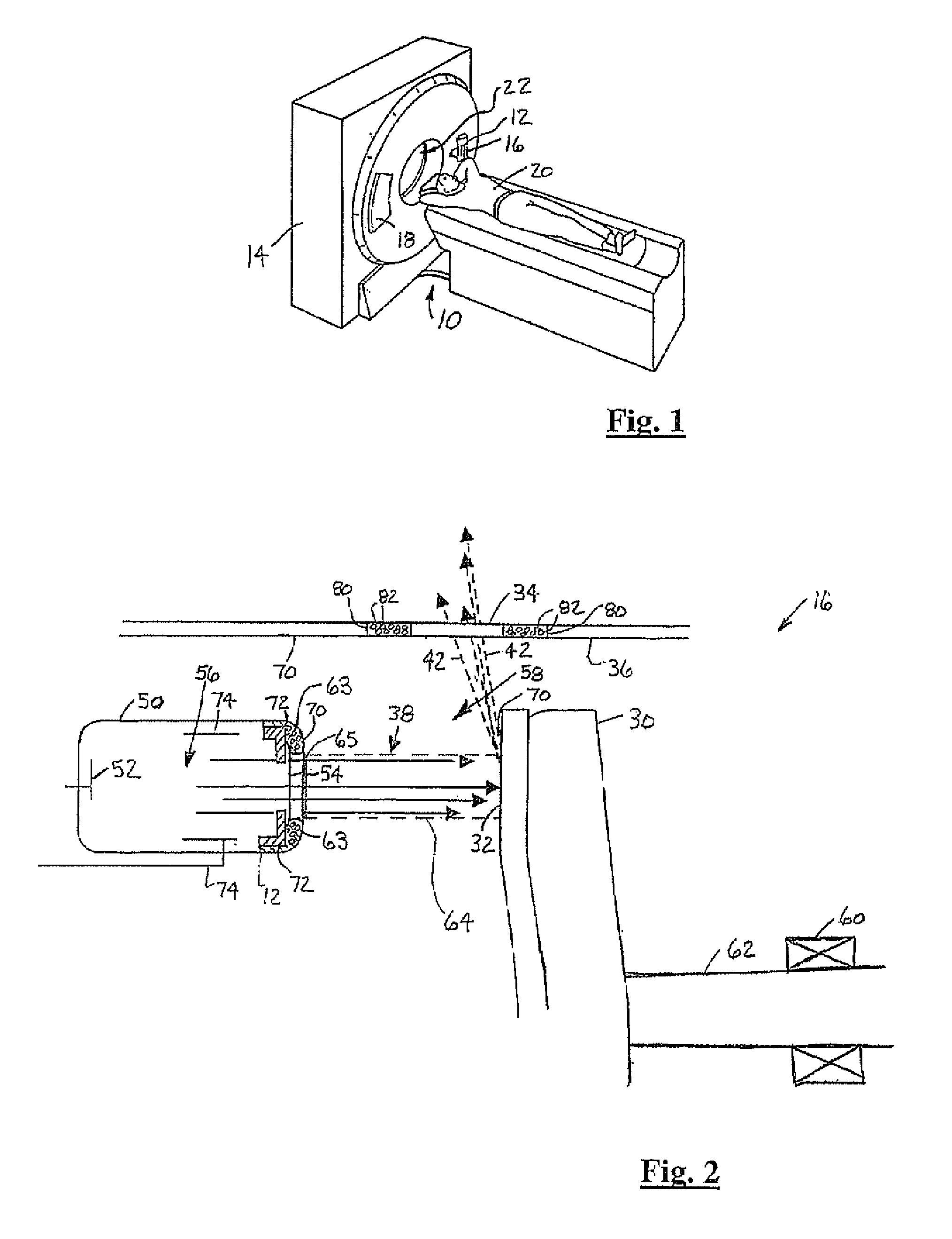
[0020] In each of the following figures, the same reference numerals are used to refer to the same components. While the present invention is described with respect to a method and apparatus for supplying and directing electrons on a target within an imaging tube, the present invention may be adapted to be used in various systems having various modalities including: X-ray systems, radiography systems, angiography systems, cardiography systems, computed tomography systems, or other systems that require the supply and direction of electrons on a target and / or employing more than one of the above systems.

[0021] In the following description, various operating parameters and components are described for one constructed embodiment. These specific parameters and components are included as examples and are not meant to be limiting.

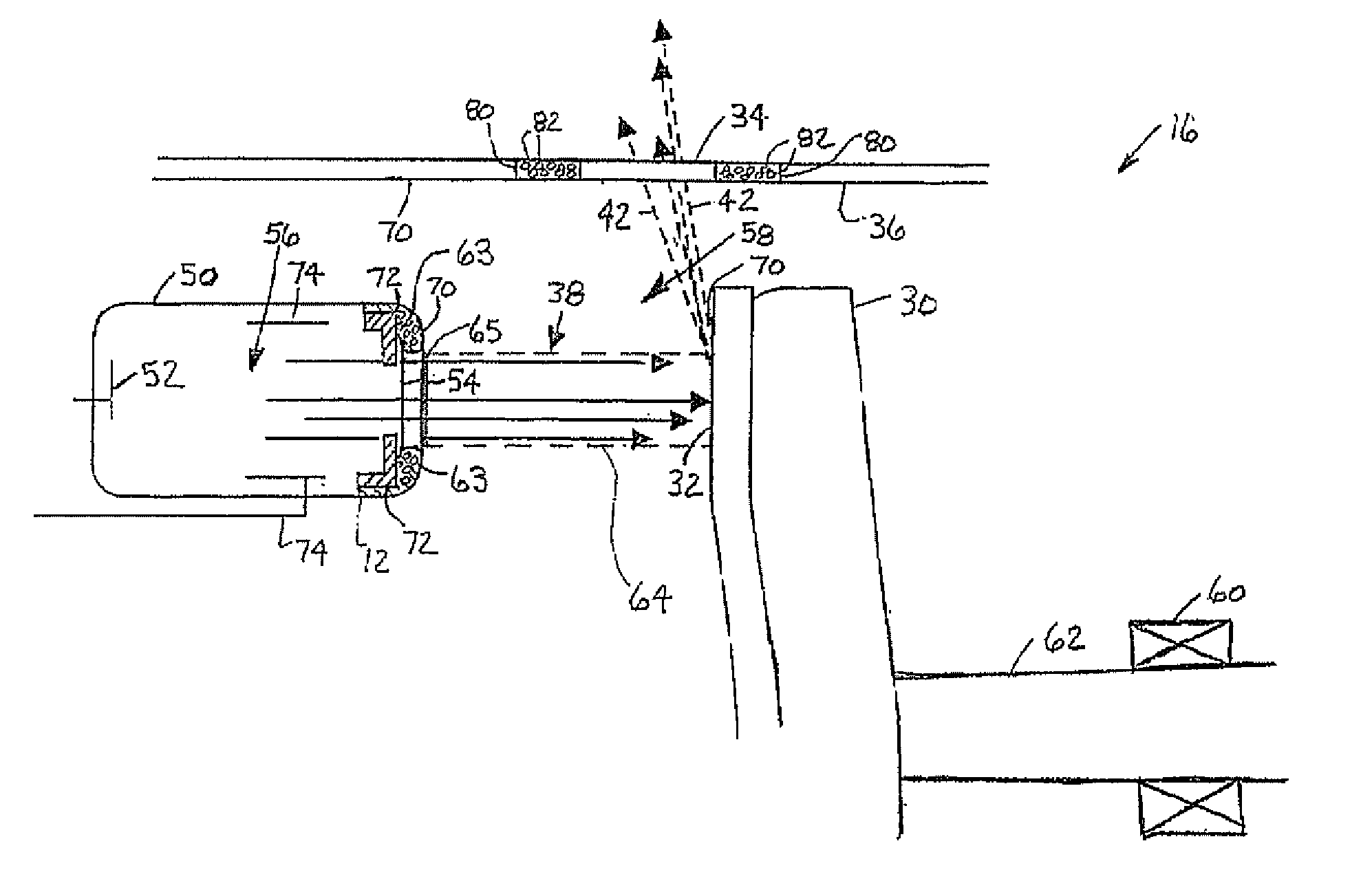
[0022] Also, in the following description the term “target” may refer to any component within an imaging tube for which electrons are emitted, directed, and imp...


PUM


Abstract

A sealed electron beam source (12) for an imaging tube (16) is provided. The beam source (12) includes a source housing (50) with a source window (54) having a first voltage potential and a source electrode (52) having a second voltage potential. The source electrode (52) generates electrons and emits the electrons through the source window (54) to a target (32) that is external to the source housing (50). A method of supplying and directing electrons on the target (32) within the imaging tube (16) is also provided. The method includes forming the source housing (50) over the source electrode (52) and sealing the source housing (50). The electrons are generated and emitted from the source electrode (52) and directed through the source window (54) to the target (32).

Description

BACKGROUND OF INVENTION [0001] The present invention relates generally to x-ray systems, and more particularly to a method and apparatus for supplying and directing electrons on a target within an imaging tube. [0002] There is a continuous effort to increase x-ray imaging system scanning capabilities. Customers desire the ability to perform longer scans at high power levels. The increase in scan time at high power levels allows physicians to gather images and constructions in a matter of seconds rather than several minutes as with previous x-ray imaging systems. Although the increase in imaging speed provides improved imaging capability, it causes new constraints and requirements for the functionality of the x-ray imaging systems. [0003] X-ray imaging systems include an imaging tube. The imaging tube generates x-rays across a vacuum gap between a cathode and an anode. In order to generate the x-rays, a large direct current (DC) voltage potential is created across the vacuum gap allo...

Claims


Application Information

Patent Timeline
Patent Type & Authority Applications(United States)
IPC IPC(8): A61B6/03H01J33/02H01J35/06H01J35/08H01J35/10H01J35/12
CPCA61B6/032A61B6/4488A61B6/4021H01J35/06H01J33/02H01J35/066
Inventor PRICE, J. SCOTTDUNHAM, BRUCE M.
Owner GE MEDICAL SYST GLOBAL TECH CO LLC
Why Eureka
Try Eureka