
Continuously variable transmission

Inactive Publication Date: 2005-06-02
FALLBROOK INTPROP COMPANY
View PDF99 Cites 74 Cited by
  • Summary
  • Abstract
  • Description
  • Claims
  • Application Information

AI Technical Summary

Problems solved by technology

However, the success of these traditional solutions has been limited.
However, the use of iris plates can be very complicated due to the large number of parts that are required to adjust the iris plates during transmission shifting.
Another difficulty with this transmission is that it has a guide ring that is configured to be predominantly stationary in relation to each of the rollers.
Since the guide ring is stationary, shifting the axis of rotation of each of the traction rollers is difficult.
A key limitation of this design is the absence of means for generating and adequately controlling the axial force acting as normal contact force to keep the input disc and output disc in sufficient frictional contact against the balls as the speed ratio of the transmission changes.
This excessive axial force lowers efficiency and causes the transmission to fail significantly faster than if the proper amount of force was applied for any particular gear ratio.
The excessive force also makes it more difficult to shift the transmission.

Method used


Image

  • Continuously variable transmission
  • Continuously variable transmission
  • Continuously variable transmission

Examples


examples

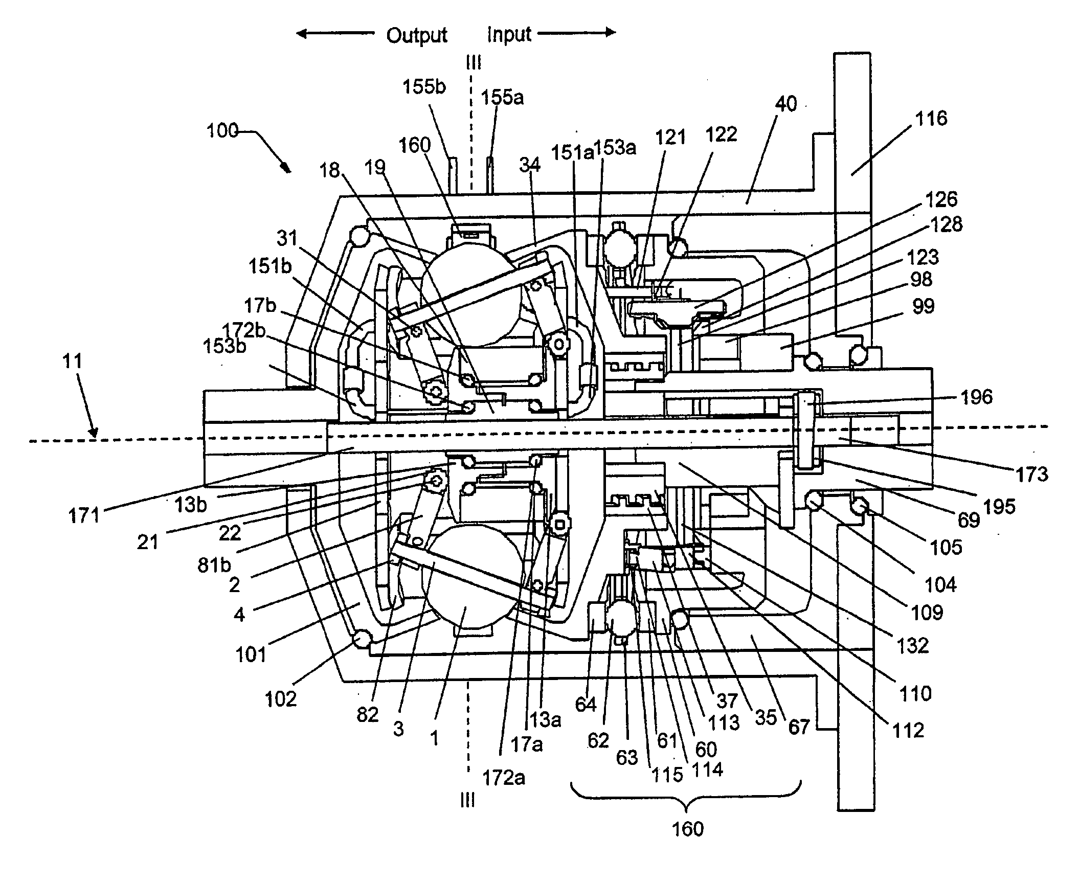
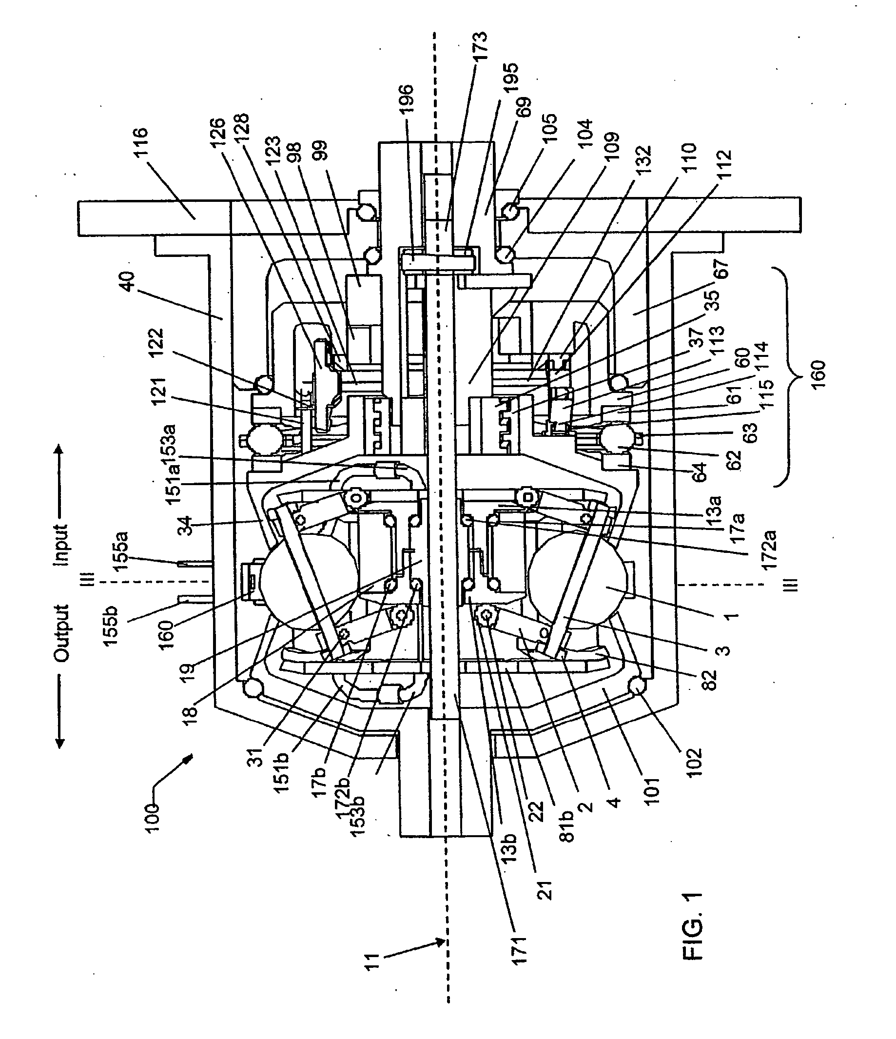
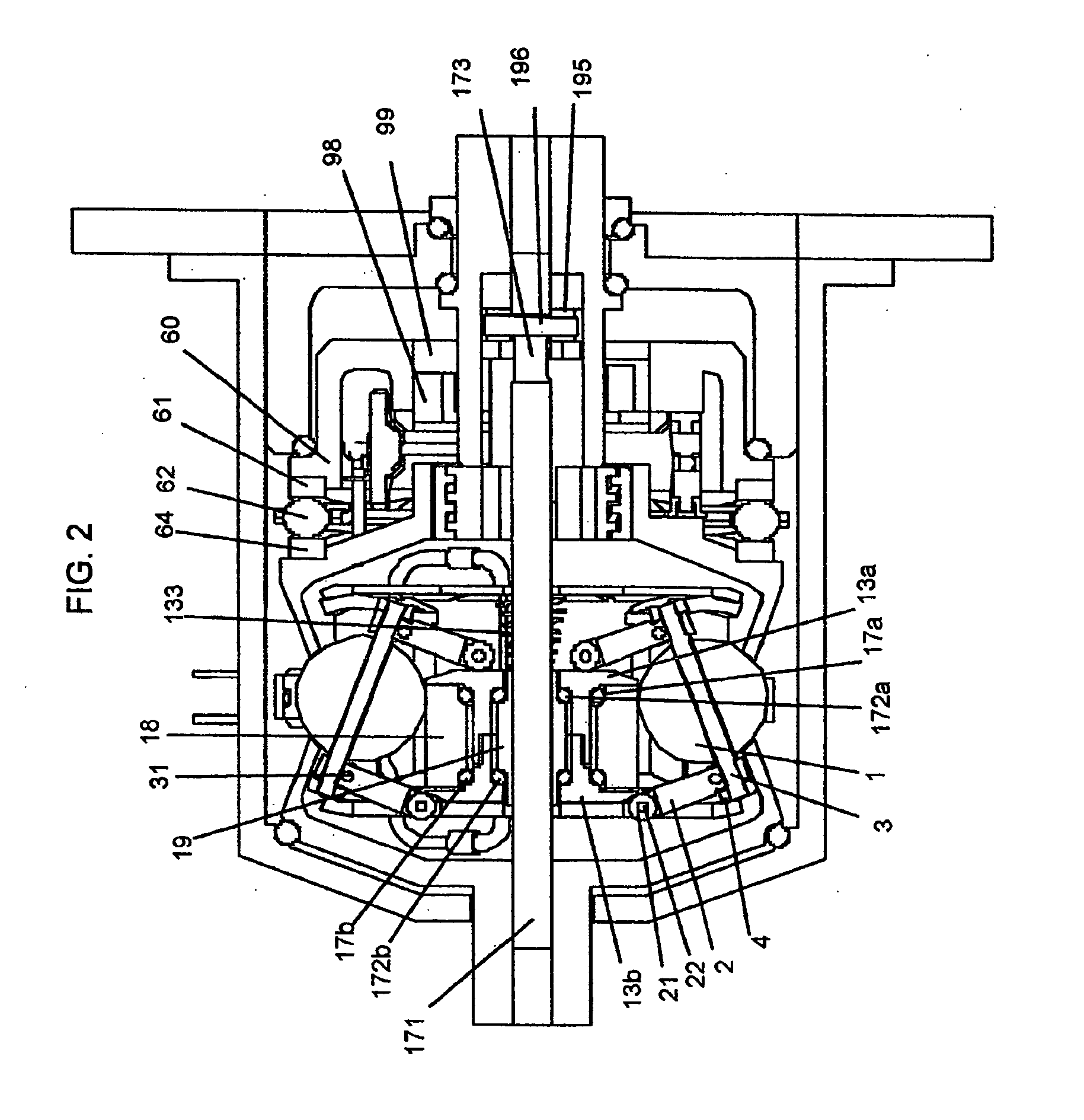
[0192] Each of these variations may have advantageous characteristics for particular applications. The variations can be modified and controlled as necessary to achieve the goals for any particular application. Specific embodiments will now be described and illustrated that employ some of the variations described herein and / or listed in the above tables. FIGS. 36a, b, and c illustrate one embodiment of a transmission 3600 that is a variation having one source of torque input and that supplies two sources of torque output. As before, only the significant differences between the embodiment illustrated in FIGS. 36a, b and c and the previously illustrated and described embodiments will be described. Furthermore, the components illustrated are being provided to illustrate to one of skill in the art how to provide power paths and torque output sources that have not been previously illustrated. It is fully understood that many additional components can and will be utilized for operational ...


PUM

PropertyMeasurementUnit
Fractionaaaaaaaaaa
Lengthaaaaaaaaaa
Lengthaaaaaaaaaa

Abstract

A variable speed transmission having a plurality of tilting balls and opposing input and output discs is illustrated and described that provides an infinite number of speed combinations over its transmission ratio range. The use of a planetary gear set allows minimum speeds to be in reverse and the unique geometry of the transmission allows all of the power paths to be coaxial, thereby reducing overall size and complexity of the transmission in comparison to transmissions achieving similar transmission ratio ranges.

Description

RELATED APPLICATIONS [0001] This application is a continuation of, and incorporates by reference in its entirety, U.S. patent application Ser. No. 10 / 788,736, filed on Feb. 26, 2004, which claims priority from U.S. Provisional Application No. 60 / 450,965 filed Feb. 28, 2003, U.S. Provisional Application No. 60 / 494,376 filed Aug. 11, 2003, U.S. Provisional Application No. 60 / 512,600 filed Oct. 16, 2003 and U.S. Provisional Application 60 / 537,938 filed Jan. 21, 2004. The entire disclosure of each of these applications is hereby incorporated by reference.BACKGROUND OF THE INVENTION [0002] 1. Field of the Invention [0003] The field of the invention relates generally to transmissions, and more particularly the invention relates to continuously variable transmissions. [0004] 2. Description of the Related Art [0005] In order to provide a continuously variable transmission, various traction roller transmissions in which power is transmitted through traction rollers supported in a housing bet...

Claims


Application Information

Patent Timeline
IPC IPC(8): B62M9/08B62M11/04B62M11/14F16H15/28F16H15/40F16H37/08F16H61/664
CPCB62M9/08Y10T29/49464B62M11/14F16H15/28F16H15/40F16H15/503F16H15/52F16H37/084F16H37/0853F16H37/086F16H61/6649F16H63/067F16H2037/101F16H15/50Y10T408/65B62M11/04F16H37/02F16H2037/088
Inventor MILLER, DONALD C.ALLEN, DAVID J.SMITHSON, ROBERT A.
Owner FALLBROOK INTPROP COMPANY
Learn More