Eureka AIR delivers breakthrough ideas for toughest innovation challenges, trusted by R&D personnel around the world.

Lighter

a technology of lighter and upper cover, applied in the field of lighter, can solve the problems of high rate of unqualified products, complex structure, and easy abrasion of the connection between the upper cover and the bracket, and achieve the effects of simple and rational assembly, simple structure, and easy assembly

Inactive Publication Date: 2005-06-02
WONG CHI LAM
View PDF27 Cites 71 Cited by
  • Summary
  • Abstract
  • Description
  • Claims
  • Application Information

AI Technical Summary

Benefits of technology

[0003] One objective of the present invention is to provide a lighter with an upper cover to overcome the above defects of the prior art and have simple structure, easy process of assembly and low cost.
[0005] The lighter with an upper cover according to the present invention is simple in structure and easy in assembly. Since there is provided with a connector, the variation to the structure of the upper cover and the case of the lighter may achieve simple and rational assembly of the case with low cost and simple manufacture.

Problems solved by technology

Currently, lighters with upper covers on market have their upper covers connected to brackets of combustion devices, which disadvantageously make the structures complicated and the connections between the upper covers and the brackets vulnerable to abrasion.
Besides, it is relatively difficult to manufacture and assemble the lighter with such structure, which may lead to high rate of unqualified products, and furthermore, if there is any failure in the connection, it would be much difficult to fix it.
Disadvantages of such structure are that the structure is complicated, the proportion of unqualified products is high due to the application of point-welding process to the connection, and the overall aesthetic effect of the lighter is damaged by possible concave welding spots caused by high temperature welding.

Method used


Image

  • Lighter
  • Lighter
  • Lighter

Examples


Embodiment Construction

[0011] The present invention now will be described in detail with reference to the embodiments and drawings.

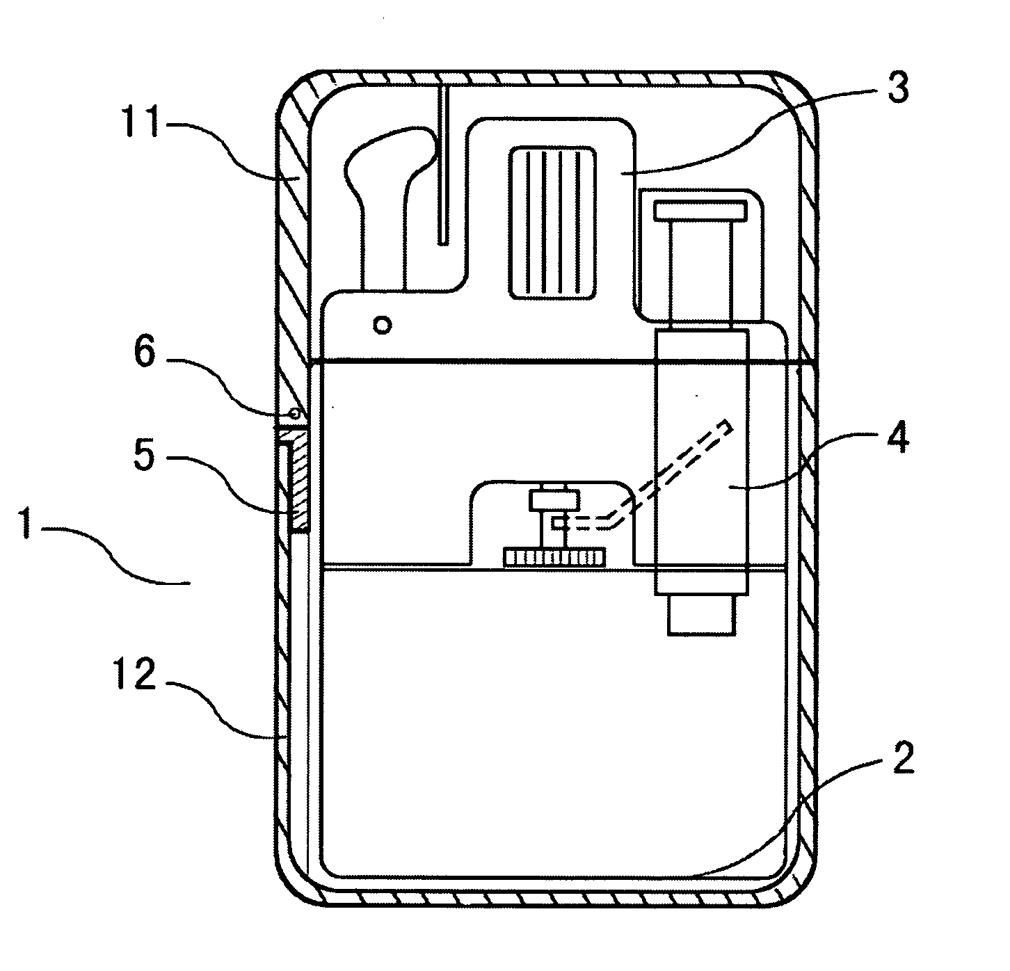
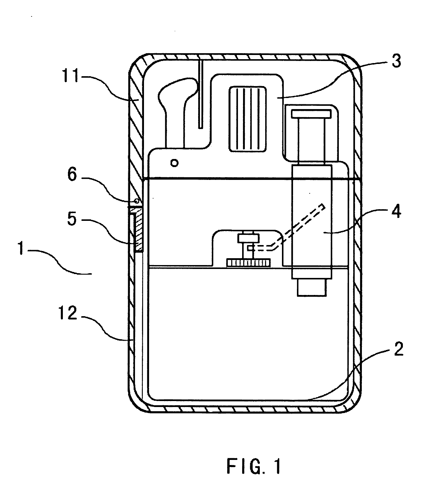
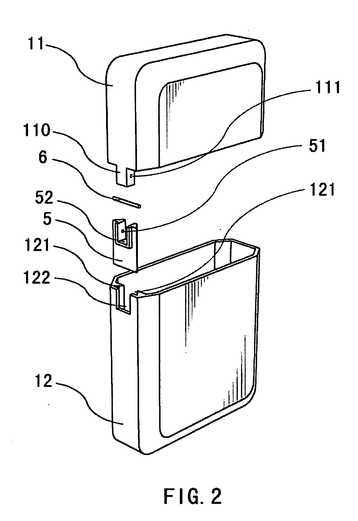
[0012] Refer to FIG. 1, a lighter comprises a lighter housing 1, a gas container 21 for containing liquid inflammable fuel gas, a combustion device 3 connecting to said container 2, and an igniter 4 for igniting inflammable gas in said combustion device 3, wherein said housing 1 includes an upper cover 11 and a case 12. At one side of said upper cover 11 there is a protuberance 110 having a small hole 111 thereon (Refer to FIG. 2).

[0013] Refer to FIGS. 2 and 3, there is a connector 5 between said upper cover 11 and said case 12 in the lighter housing. The connector 5 is disposed below the protuberance 110 of the upper cover 11 to connect the upper cover 11 and case 12. The connector 5 includes a recess portion 52 coupling with the protuberance 110 of the upper cover 11 and having transverse holes 51 on both sides of the recess portion 52. A bolt 6 is provided to rotationally...


PUM


Abstract

A lighter comprises a lighter housing, a gas container for storing liquid inflammable gas, a combustion device connected to the gas container, and an igniter for igniting inflammable gas in the combustion device. The housing includes an upper cover and a case, wherein one side of the upper cover includes a protuberance forming a small hole thereon; a connector disposed below the protuberance of the upper cover for connecting the upper cover and the case, wherein the connector includes a recess portion coupling with the protuberance and having transverse holes on both sides of the recess portion; and a bolt for rotationally connecting the protuberance and the recess portion; wherein the case has at its edge port a longitudinal groove connected to the connector and having an opening at the edge port of the groove to couple with the protuberance of the upper cover.

Description

FIELD OF THE INVENTION [0001] The present invention relates to a lighter, and in particular, to a lighter with an upper cover. BACKGROUND OF THE INVENTION [0002] Currently, lighters with upper covers on market have their upper covers connected to brackets of combustion devices, which disadvantageously make the structures complicated and the connections between the upper covers and the brackets vulnerable to abrasion. Besides, it is relatively difficult to manufacture and assemble the lighter with such structure, which may lead to high rate of unqualified products, and furthermore, if there is any failure in the connection, it would be much difficult to fix it. In addition to such lighters, there is another type of lighter which has its upper cover integrated with the lighter housing. Disadvantages of such structure are that the structure is complicated, the proportion of unqualified products is high due to the application of point-welding process to the connection, and the overall a...

Claims


Application Information

Patent Timeline
IPC IPC(8): F23Q2/40
CPCF23Q2/40Y10T16/5525Y10T16/553
Inventor WONG, CHI LAM
Owner WONG CHI LAM
Why Eureka
Eureka Blog
Learn More