
Device and method for coding video data

a video data and interlaced frame technology, applied in the field of interlaced frame coding, can solve the problems of high cost in time or calculation, hardly conceivable real-time application coding mode, etc., and achieve the effect of improving coding bit rate and reducing coding costs

Active Publication Date: 2005-06-02
BURLEY LICENSING LLC
View PDF11 Cites 3 Cited by
  • Summary
  • Abstract
  • Description
  • Claims
  • Application Information

AI Technical Summary

Benefits of technology

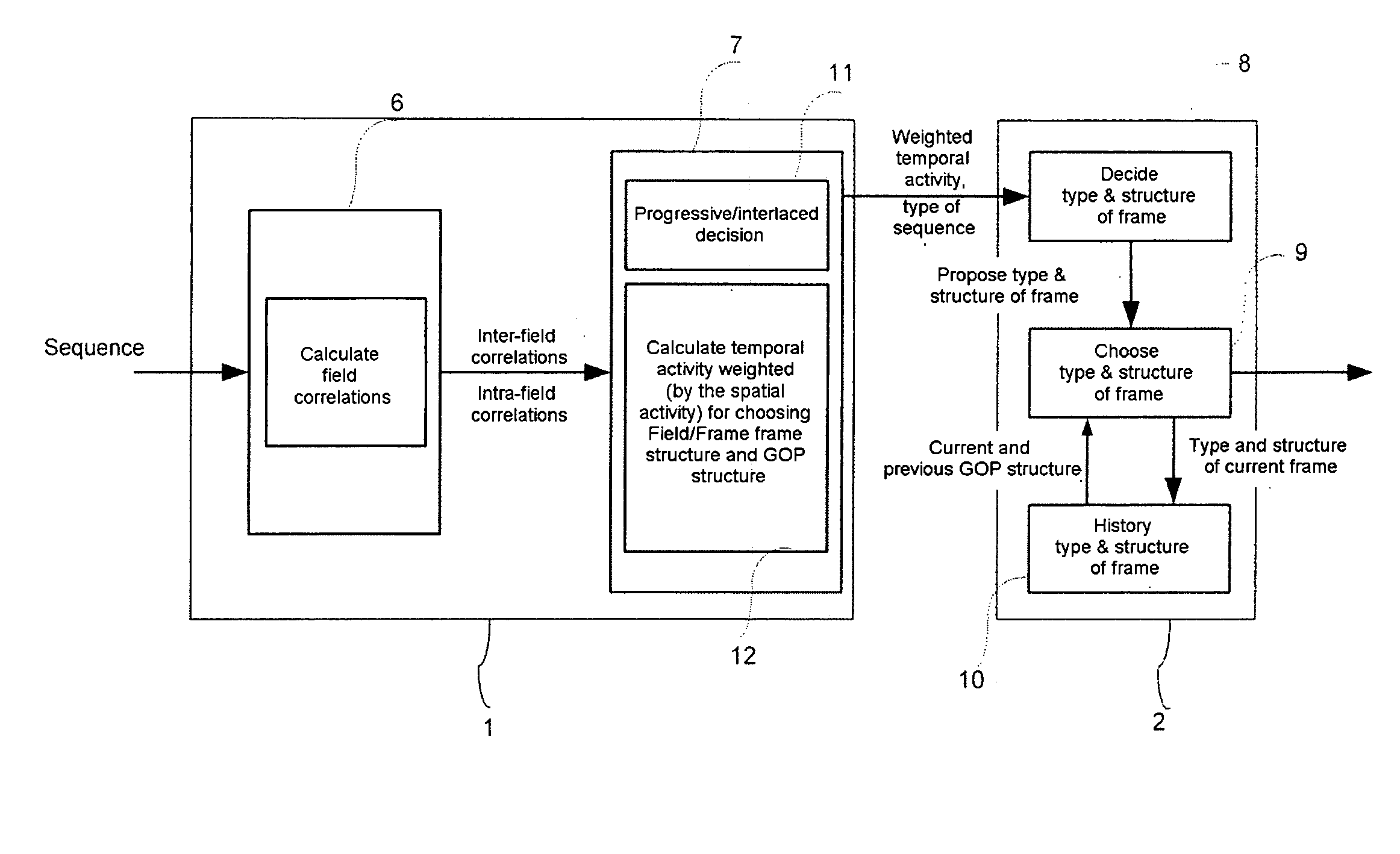
[0022] The invention can enable a reduction in the number of calculations of 30 to 60% with respect to the approach of the reference model. This optimization of the calculations is not done to the detriment of coding quality: the invention is more particularly aimed at applications of high coding quality.
[0025] The coupling of the choice of the frame / field coding structure and of the GOP structure can make it possible to exceed the performance of the reference model of the standard.
[0030] This is particularly beneficial in the case of sequences exhibiting weak temporal activity, the coding in bi-predictive mode being fairly inexpensive.
[0032] This may enable a reduction in the coding costs and therefore an improvement in the coding bit rate.

Problems solved by technology

Such a mode of coding is hardly conceivable for real-time applications since it is too expensive in terms of time or calculation means: it necessitates the calculation of frame structure field predictions, frame structure frame predictions, field structure field predictions, i.e. three times as many calculations as the coding of a progressive source (frame structure frame predictions) which is already critical for a standard television format in the current state of the art.
Moreover, the reference model of the standard implements a fixed GOP structure, this not guaranteeing that the choice of coding, although made in a-posteriori mode, will make it possible to obtain the best coding in terms of bit rate / distortion compromise.

Method used


Image

  • Device and method for coding video data
  • Device and method for coding video data
  • Device and method for coding video data

Examples


Embodiment Construction

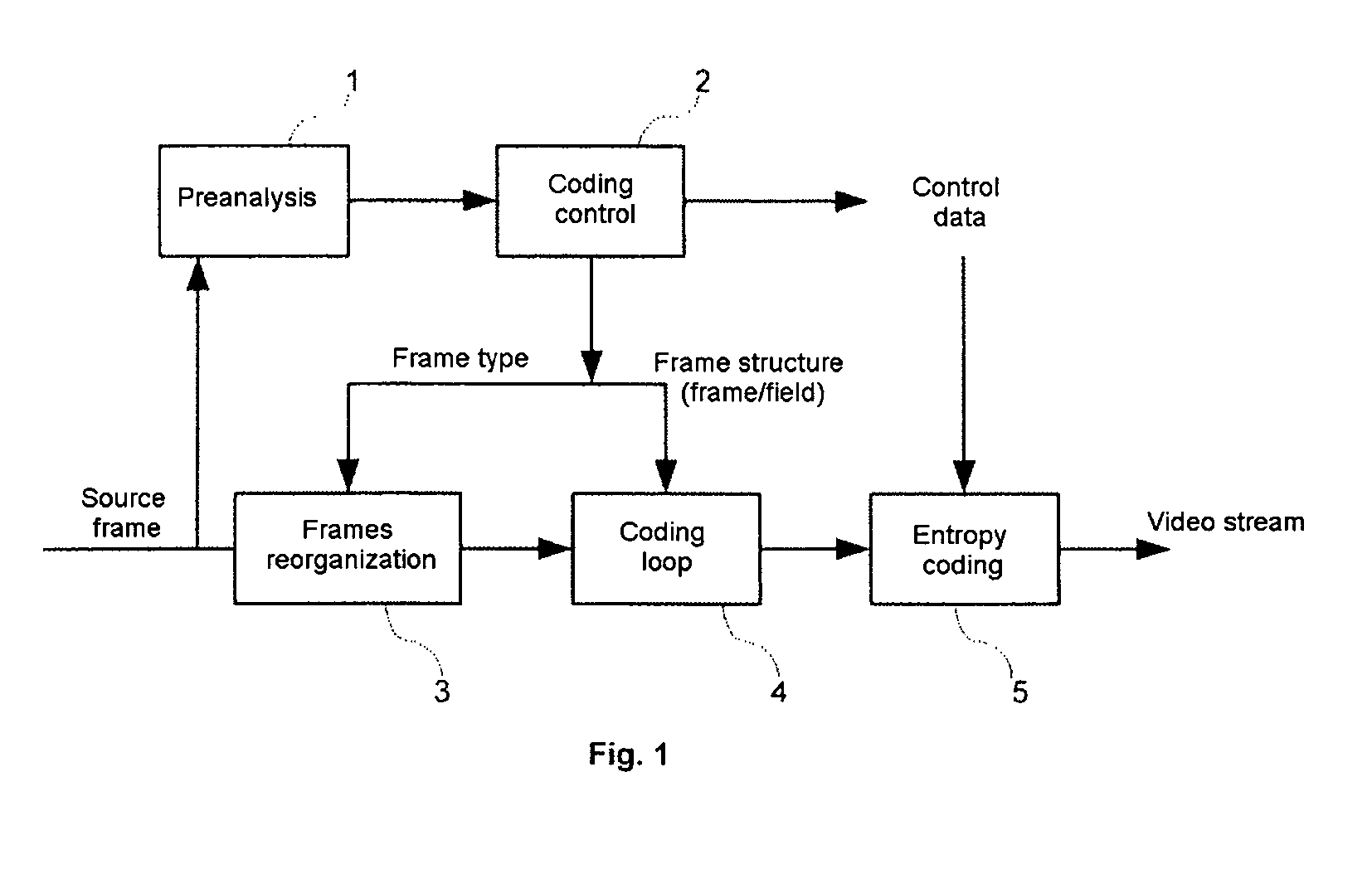
[0044]FIG. 1 represents a coding device according to the preferred embodiment. The coding device comprises a preanalysis module 1 which receives as input the frame sequences originating from the video stream to be coded. The video stream is also transmitted to the input of a module 3 for reorganizing the frames.

[0045] The output of the frames reorganization module 3 is connected to the input of a coding loop 4 whose output is connected to an entropy coding module 5 which delivers the coded video data stream as output.

[0046] The preanalysis module 1 is connected as output to the input of a coding control module 2 which provides the entropy coding module 5 with control data, which provides the frames reorganization module 3 with the type of frame to be coded and which provides the coding loop 4 with the type of coding structure, namely a coding of frame or field type.

[0047] The entropy coding module 5 provides the coded video steam as output.

[0048] The coding loop 4 is a coding lo...


PUM


Abstract

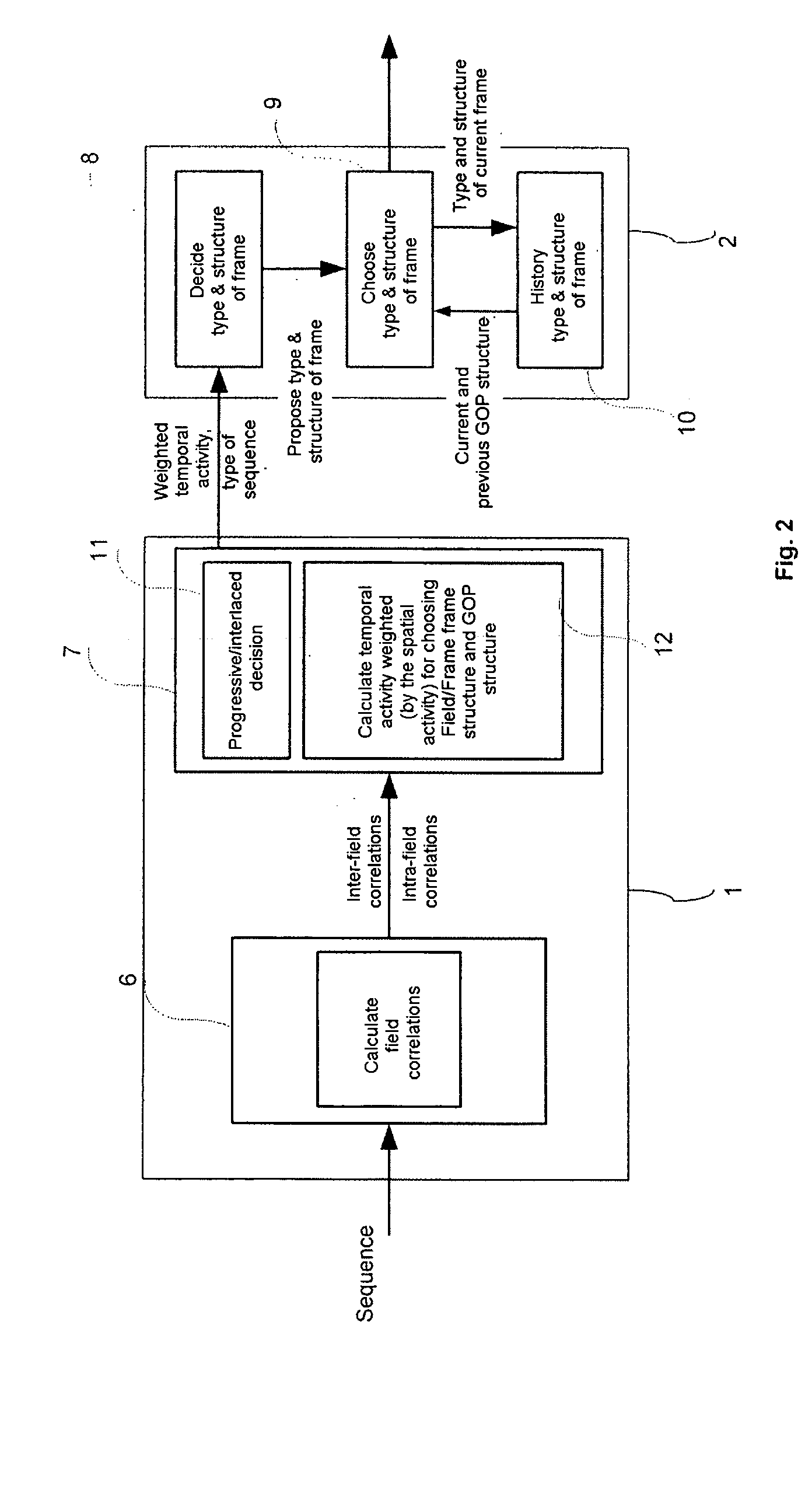
The invention relates to a device for coding video frame sequences, comprising means (1) for measuring the spatial activity of the video frames to be coded, means (1) for measuring the temporal activity of the video frames to be coded, means (2) for coding the frames as a frame structure or as a field structure. According to the invention, the means (2) for coding the frames as a frame structure or as a field structure are able to choose the field or frame structure dynamically as a function of the measurements of spatial and temporal activity of the said frame.

Description

BACKGROUND OF THE INVENTION [0001] The invention applies more particularly to the coding of interlaced frames, that is to say those composed of two fields sampled at distinct instants. [0002] The coding of video frames is necessary for the transmission of digital video data in limited bandwidth networks as well as for applications where storage constitutes a limit. [0003] The compression of digital video data without significant degradation of quality is possible when the video sequences display a high degree of spatial redundancy, of spectral redundancy, of temporal redundancy, of psycho-visual redundancy. [0004] In the course of the last few years, interest in respect of multimedia has led to the emergence of new compression standards and has seen the development of standards such as MPEG-2 and more recently H.264 defined under the reference: ITU-T Rec. H.264|ISO / IEC 14496-10 AVC. [0005] These standards are aimed at a vast gamut of applications with varied demands with regard to b...

Claims


Application Information

Patent Timeline
Patent Type & Authority Applications(United States)
IPC IPC(8): H04N7/24H04N19/50
CPCH04N19/147H04N19/172H04N19/149H04N19/61H04N19/107H04N19/177H04N19/114H04N19/124H04N19/14H04N19/137H04N19/112
Inventor DUCLOUX, XAVIERALEXANDRE, PATRICENOBLET, LUDOVIC
Owner BURLEY LICENSING LLC
Learn More