
Telephone communication system over a single telephone line

a telephone communication system and telephone line technology, applied in the field of telephone communication networks, can solve the problems of requiring additional wires, labor-intensive and expensive wiring routing and installation, and aesthetically undesirabl

Inactive Publication Date: 2005-06-02
CONVERSANT INTPROP MANAGEMENT INC
View PDF99 Cites 8 Cited by
  • Summary
  • Abstract
  • Description
  • Claims
  • Application Information

AI Technical Summary

Benefits of technology

"The present invention is an improved telephone system in a building that allows more voice channels to be carried over a single telephone line without requiring modification or extension of the telephone installation. The system includes at least two modules that convert between standard analog telephone signals and time-domain multiplexed voice channels, and interface with standard analog telephone equipment and signals. The modules can be integrated into the outlet or externally configured. The system also includes a kit for upgrading a pre-existing telephone installation with a line within a building. The kit includes an outlet with a connection for coupling to the line, a module for converting and interfacing with standard analog telephone equipment and signals, and a telephone line modem. The method for upgrading a pre-existing telephone installation includes providing a telephone line modem, a subscriber-line interface, a drop-and-insert multiplexer, and an outlet equipped with the necessary components. The invention allows for life-line functionality and facilitates the use of standard analog telephone equipment in a multiple voice channel network over a single telephone line."

Problems solved by technology

The routing and installation of such wiring is both labor-intensive and expensive.
Adding the new wiring on the exterior of the wall is less expensive, but may be aesthetically undesirable.
However, the same problem of needing additional wires is encountered in this case when a third or fourth subscriber line is required.
In such a case, a private automatic branch exchange cannot easily be employed, unless effort is made to modify the wiring into ‘star’ topology.

Method used


Image

  • Telephone communication system over a single telephone line
  • Telephone communication system over a single telephone line
  • Telephone communication system over a single telephone line

Examples


Embodiment Construction

[0053] The principles and operation of a network according to the present invention may be understood with reference to the drawings and the accompanying description. The drawings and descriptions are conceptual only. In actual practice, a single component can implement one or more functions; alternatively, each function can be implemented by a plurality of components, and circuits. In the drawings and descriptions, identical reference numerals indicate those components which are common to different embodiments or configurations.

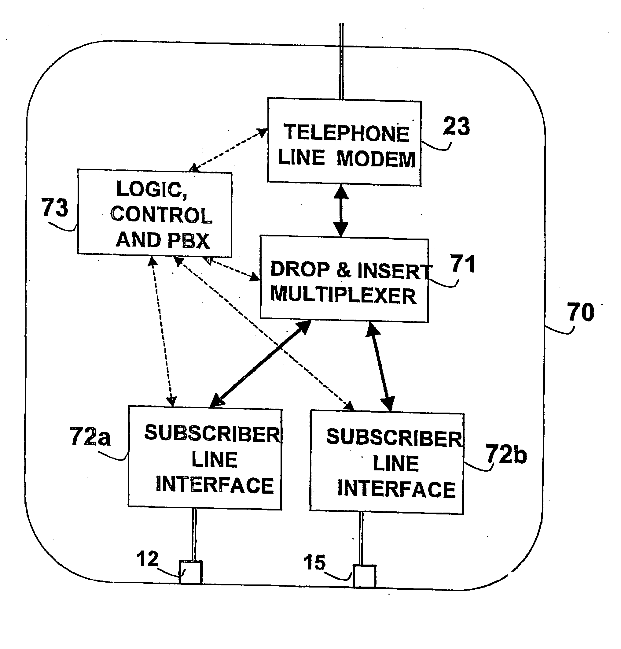
[0054] A first embodiment of the present invention is based on an adapter module (hereinafter denoted as a “module”), which enables the connection of a standard telephone set to the data communication network over the telephone line. FIG. 7 illustrates the functionality of a module 70. Module 70 has two ports: one for connecting to the telephone line and the other for connecting to one or more telephone sets. The module interfaces the data communication net...


PUM


Abstract

An improved telephone system over a single telephone line within a residence or other building is disclosed, supporting exchange features and enabling easy expansion for multiple external lines. The existing telephone wiring is used as the medium for a local data communication network carrying multiple voice channels. In each outlet, one or more voice channels are converted into a standard telephone-line interface. Life-line functionality is facilitated by using the lower band of the spectrum isolated from the data communication network, and a dedicated connector in the outlet provides access to this band. External telephone feeders are converted to digital form for interfacing to the in-home data communication network.

Description

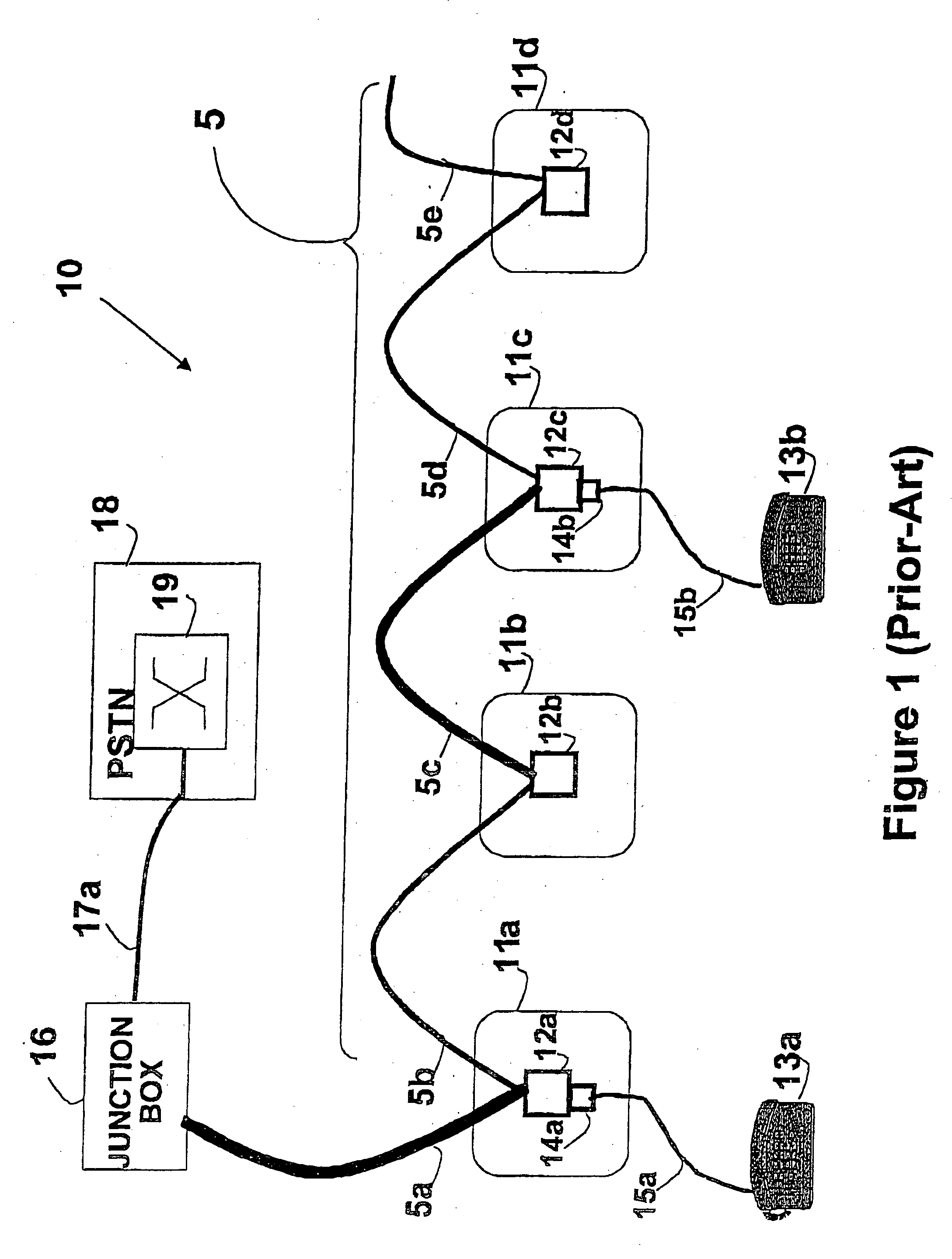
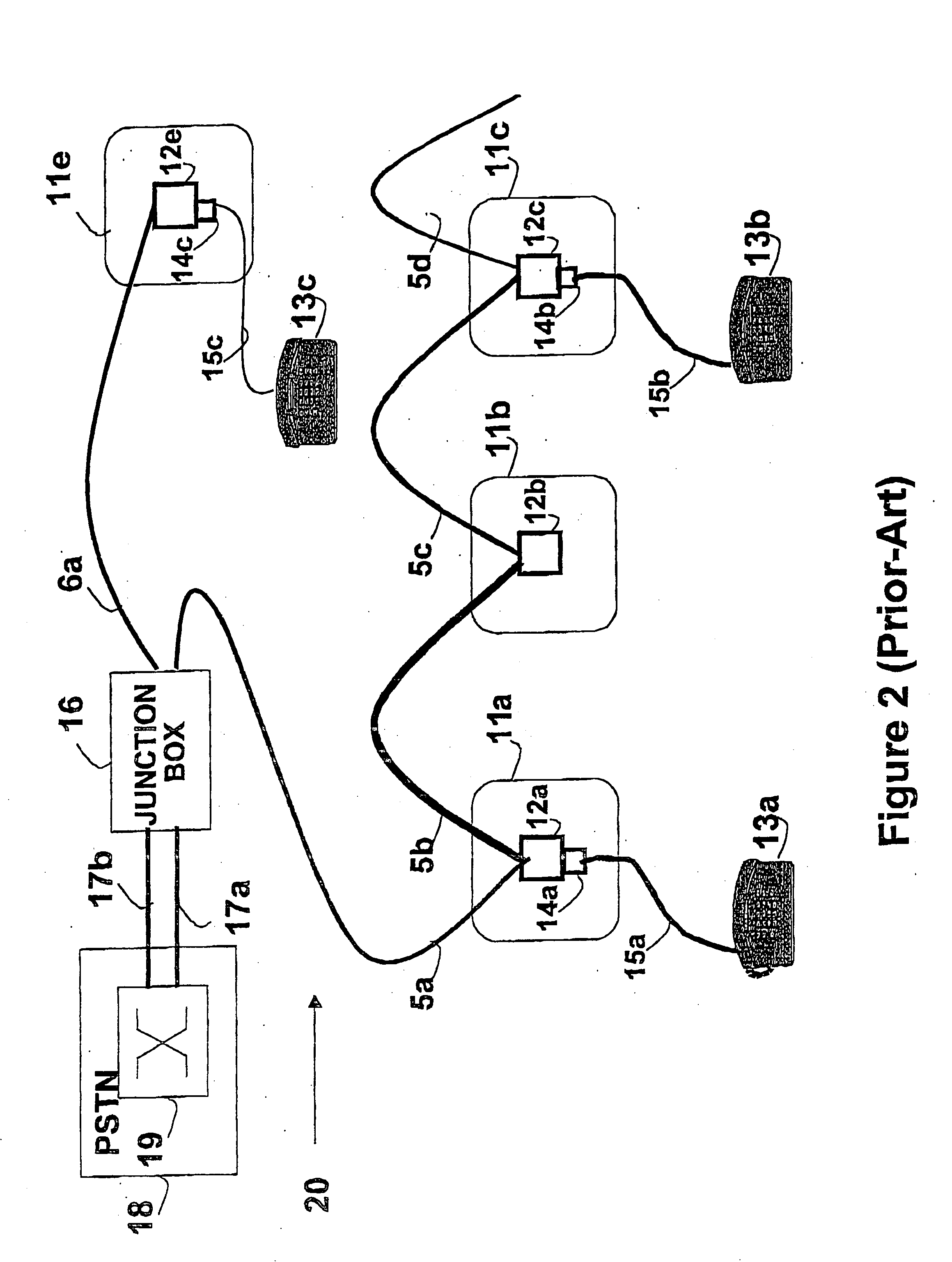
FIELD OF THE INVENTION [0001] The present invention relates to the field of telephony communication networks, and, more specifically, to the networking of telephone sets within a building over single telephone line. BACKGROUND OF THE INVENTION [0002] There is a growing need for expanded telephone communication capabilities within the home. This need is driven by two major factors; the increasing use of additional outside lines and the desirability of exchange functionality within the home, such as for intercom systems, Telephone Wiring [0003] An in-home telephone service usually employs two or four wires, and is accessed via telephone outlets into which the telephone sets are connected. FIG. 1 shows the wiring configuration of a prior-art telephone system 10 for a residence or other building, wired with a residential telephone line 5. The residential telephone line 5 consists of single wire pair which connects to a junction box 16, which in turn connects to a Public Switched Teleph...

Claims


Application Information

Patent Timeline
Patent Type & Authority Applications(United States)
IPC IPC(8): H04M1/715H04M11/00H04M9/02H04Q11/04
CPCH04L5/16H04Q2213/13389H04M9/025H04M11/062H04M11/068H04Q11/0471H04Q2213/13034H04Q2213/13082H04Q2213/13166H04Q2213/13199H04Q2213/1322H04Q2213/1323H04Q2213/13298H04Q2213/13299H04Q2213/1332H04Q2213/13334H04M1/723H04M1/715H04M9/02
Inventor BINDER, YEHUDA
Owner CONVERSANT INTPROP MANAGEMENT INC
Learn More