
Display apparatus and method

a technology of display apparatus and display screen, which is applied in the direction of identification means, electrical apparatus casings/cabinets/drawers, instruments, etc., can solve the problems of increased production costs, complicated assembly, and inefficient operation

Inactive Publication Date: 2005-06-02
SAMSUNG ELECTRONICS CO LTD
View PDF29 Cites 37 Cited by
  • Summary
  • Abstract
  • Description
  • Claims
  • Application Information

AI Technical Summary

Benefits of technology

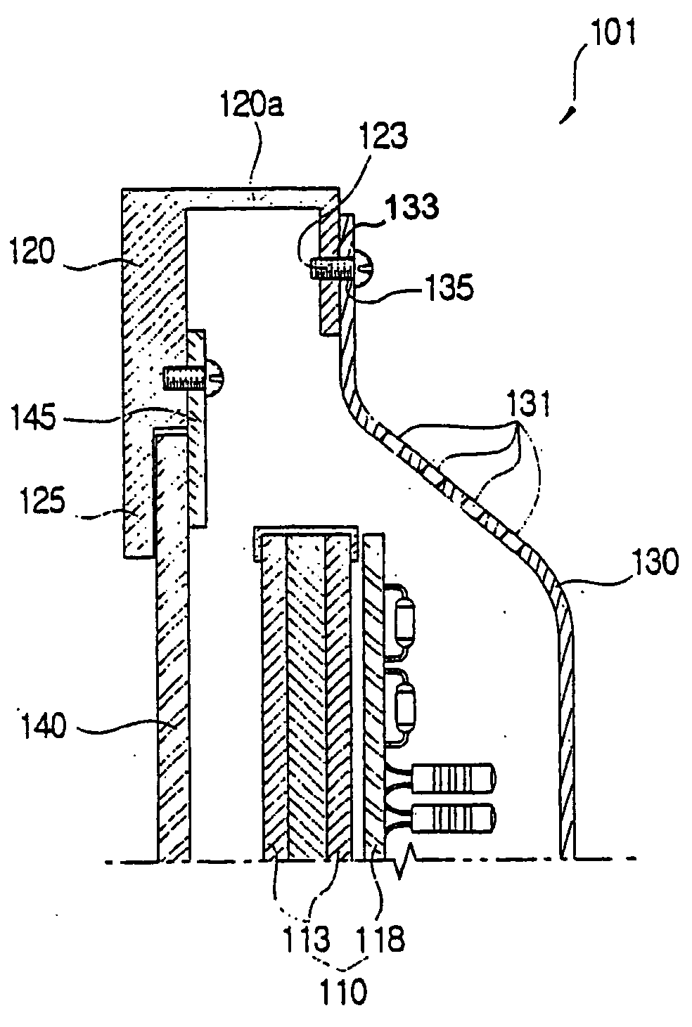
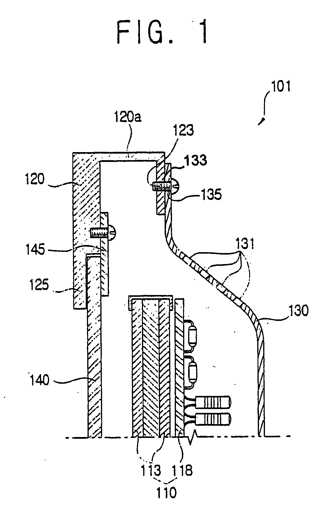
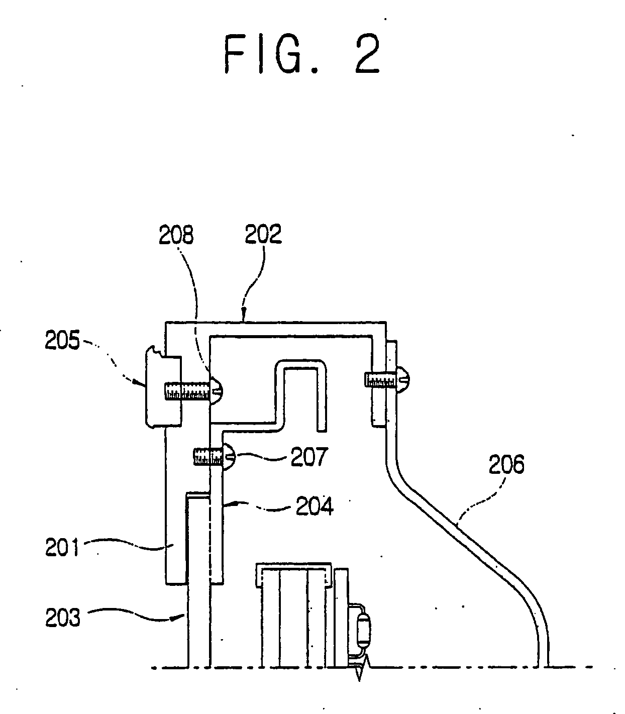
The present invention provides a display apparatus that prevents heat from being transferred from a display module to the exterior of a front casing, decreases the probability of malfunction, and improves the outward appearance of the apparatus. This is achieved by providing a display module with a front casing and a rear casing, with a plurality of air slits through which heat generated in the display module is dissipated. The front casing includes an insulator preventing the heat from being transferred to the exterior. The front casing is attached to the rear casing with a screw, and the front casing is provided with an attachment boss with which the screw is coupled without passing, and the rear casing is provided with a through hole, through which the screw passes. The insulator forms an air space insulating the lateral sides of the front casing from the display module. The front casing is made of material containing aluminum. The display apparatus also includes a filter support in front of an optical filter to shield EMI, a decorative member attached to the front casing with a screw, and a rear casing attached to the rear of the front casing to conduct EMI away from the front casing. The decorative member is nonconductive and made of material containing synthetic resin. The front casing is made of material containing aluminum.

Problems solved by technology

Thus, assembly is complicated and inefficient.
Further, since the number of components and the number of assembling processes are relatively increased, production costs are increased.

Method used


Image

  • Display apparatus and method
  • Display apparatus and method
  • Display apparatus and method

Examples


Embodiment Construction

[0041] Reference will now be made in detail to the embodiments of the present invention, examples of which are illustrated in the accompanying drawings, wherein like reference numerals refer to like elements throughout. The embodiments are described below in order to explain the present invention by referring to the figures.

[0042] A display apparatus according to an aspect of the present invention displays a picture by using a CRT (Cathode Ray Tube), an LCD (Liquid Crystal Display), or a PDP (Plasma Display Panel), etc.

[0043] Hereinafter, the display apparatus including the PDP will be described in conjunction with the accompanying drawings.

[0044] As shown in FIGS. 3 through 5, the display apparatus 1, according to an aspect of the present invention includes a display module 10, to display a picture, a front casing 20 adjacent to a front and sides of the display module 10, and a rear casing 30 provided to the rear of the display module 10.

[0045] The display module 10 includes a ...


PUM

PropertyMeasurementUnit
conductiveaaaaaaaaaa
energy transferaaaaaaaaaa
areaaaaaaaaaaa

Abstract

A display apparatus having a display module, to display a picture, includes a front casing positioned adjacent to a front and side of the display module, and a rear casing positioned in a rear of the display module and with a plurality of air slits, to dissipate heat generated in the display module. The front casing includes an insulator, to prevent the heat generated in the display module from being transferred exterior of the front casing. The display apparatus prevents heat from being transferred from a display module to the exterior of a front casing. Further, debris created while a screw is inserted does not fall toward the display module, thereby preventing the display module from a malfunction due to the fallen debris.

Description

CROSS-REFERENCE TO RELATED APPLICATIONS [0001] This application claims the benefit of Korean Patent Applications Nos. 2003-53838, filed Aug. 4, 2003, and 2003-53837, filed Aug. 4, 2003, in the Korean Intellectual Property Office, the disclosure of which is incorporated herein by reference. BACKGROUND OF THE INVENTION [0002] 1. Field of the Invention [0003] The present invention relates to a display apparatus, and more particularly, to a display apparatus structurally improved, and preventing heat generated in a display module from being transferred to a front casing. [0004] 2. Description of the Related Art [0005] Generally, a display apparatus includes a television, a monitor for a computer, etc., and includes a display module to display a picture, and a casing to support the display module. [0006] The display module displays a picture by using a CRT (Cathode Ray Tube), an LCD (Liquid Crystal Display), or an PDP (Plasma Display Panel), etc. [0007] Hereinafter, a display module incl...

Claims


Application Information

Patent Timeline
Patent Type & Authority Applications(United States)
IPC IPC(8): G02F1/13G02F1/133G09F9/35G12B9/04G12B9/10G12B15/04G12B17/02H05K5/02H05K7/20H05K9/00
CPCG02F1/133308G02F1/133385H05K7/20G02F2201/36G02F2201/46G02F2001/13332G02F1/13332
Inventor LEE, YOU-SUBAN, EUN-SERBKIM, KWEY-HYUN
Owner SAMSUNG ELECTRONICS CO LTD
Learn More