
Pyrotechnic linear inflator

a linear inflator and pyrotechnic technology, applied in the field of linear inflators, can solve the problems of low system efficiency and the need for extra space inside the vehicle to house the inflator, and achieve the effects of reducing the overall size envelope of the inflator, enhancing the ignition and burning of the gas generant composition, and reducing the cos

Inactive Publication Date: 2005-06-02
AUTOMOTIVE SYST LAB
View PDF99 Cites 23 Cited by
  • Summary
  • Abstract
  • Description
  • Claims
  • Application Information

AI Technical Summary

Benefits of technology

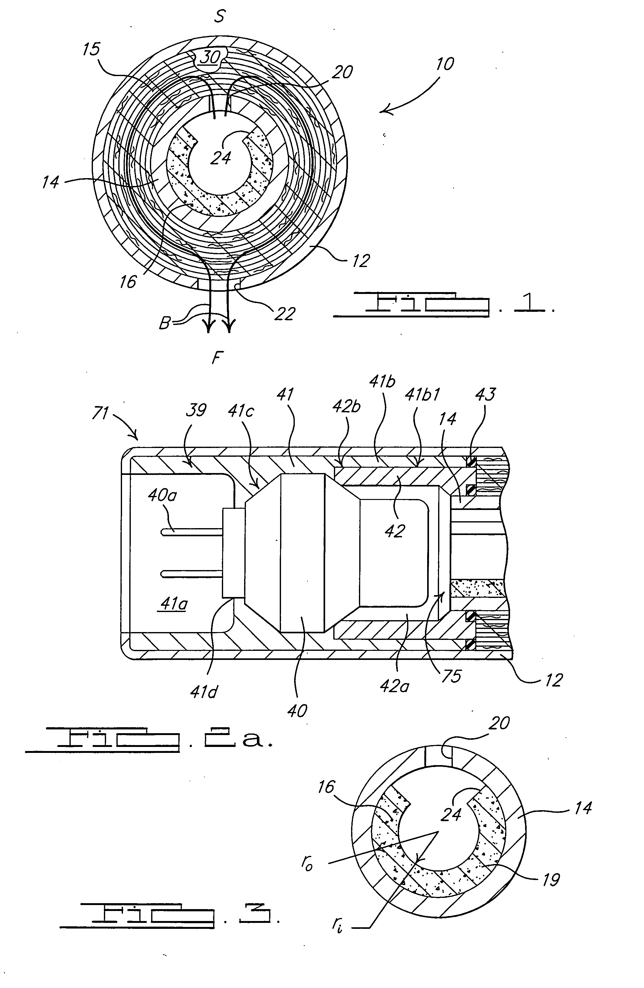
[0006] The slotted, “C”-shaped cross section of the gas generant provides a greater exposed gas generant surface area than would be achievable without the slot. This enhances the ignition and burning of the gas generant composition upon inflator activation, while also providing fluid communication between a relatively large surface area of gas generant and the inner housing orifice(s). The present inflator is also self-contained, generating and discharging gas uniformly along its length without the need for a separate conventional inflator connected to a distribution pipe. This reduces the overall size envelope of the inflator. The inflator of the present invention is also lower in cost and simpler to manufacture than many known designs.

Problems solved by technology

There are pressure losses associated with gas flow through the distribution pipe, resulting in lower system efficiencies.
In addition, extra space inside the vehicle is required to house the inflator portion of the devices.

Method used


Image

  • Pyrotechnic linear inflator
  • Pyrotechnic linear inflator
  • Pyrotechnic linear inflator

Examples


Embodiment Construction

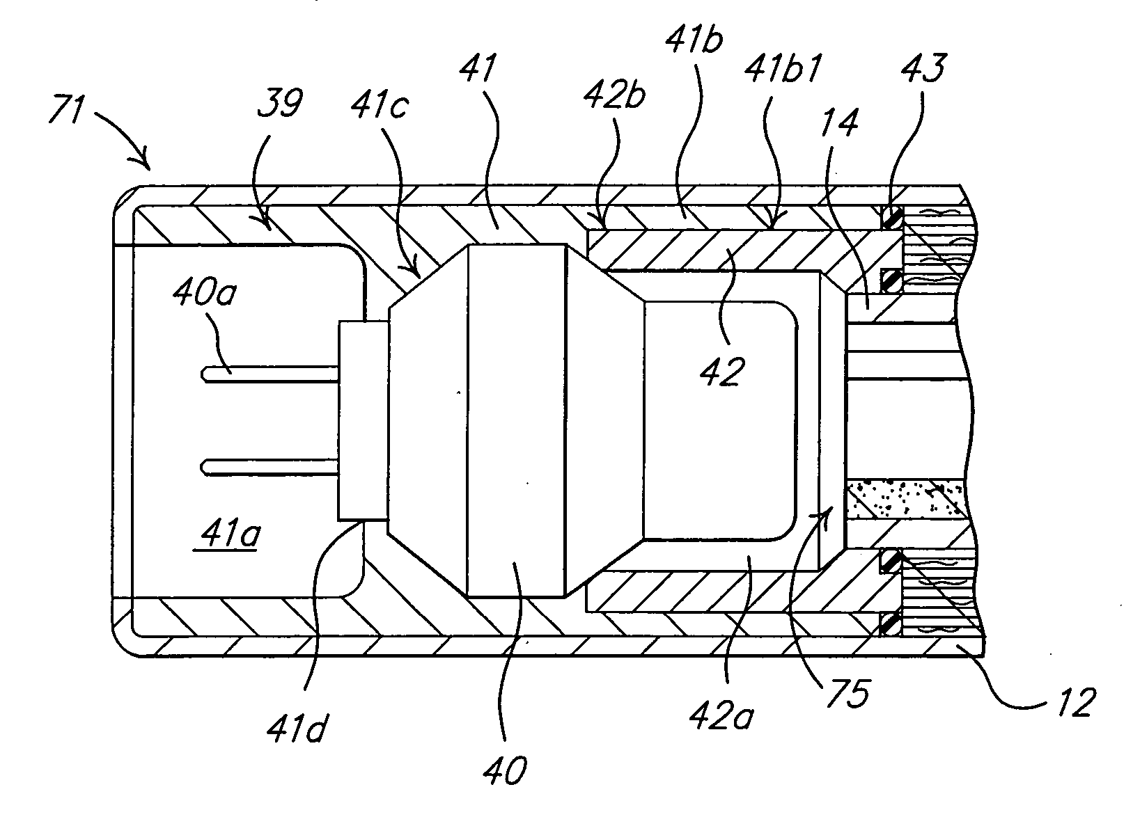
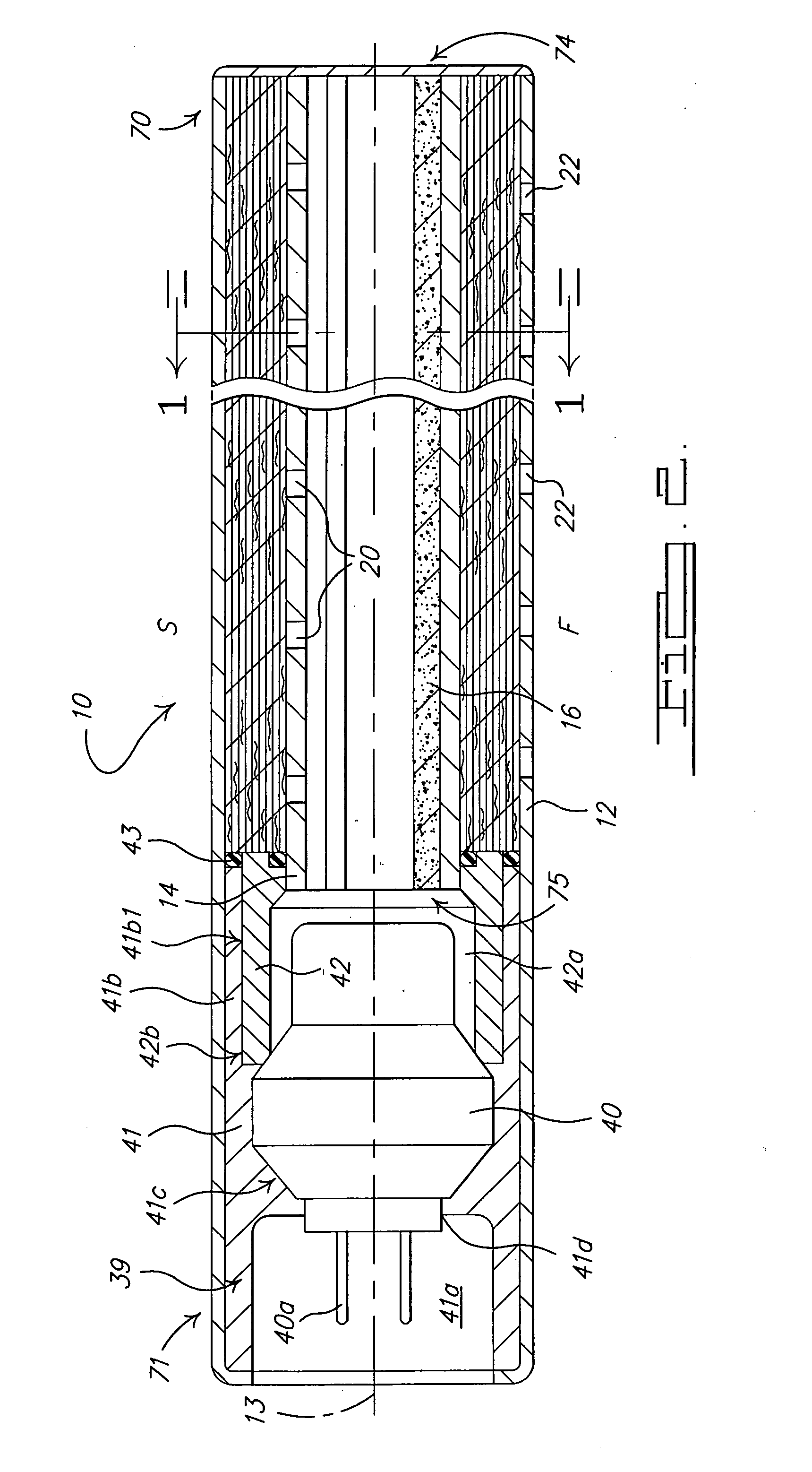
[0016]FIGS. 1 and 2 show cross-sectional view of an inflator 10 in accordance with the present invention. Inflator 10 includes an elongated outer housing 12 and an elongated inner housing 14 positioned in an interior of outer housing 12, thereby forming a cavity 30 between inner housing 14 and outer housing 12. All the component parts of inflator 10 are manufactured from materials and with processes known in the art.

[0017] Outer housing 12 includes a first end 70, a second end 71, and a longitudinal axis 13. Outer housing 12 has one or more orifices 22 formed therealong to enable fluid communication between the interior and the exterior of the outer housing. Orifice(s) 22 are adapted to convey gas produced by the combustion of a gas generant composition to an associated airbag (not shown). In the embodiment shown in FIGS. 1 and 2, orifice(s) 22 are aligned along the length of outer housing 12. Orifice(s) 22 also open from the outer housing interior toward a first side (designated “...


PUM


Abstract

An airbag inflator (10) including an elongated outer housing (12) having an interior and one or more orifices (22) formed therealong to enable fluid communication between the outer housing interior and an exterior of the outer housing (12). The outer housing orifice(s) (22) open from the outer housing interior toward a first side (F) of the inflator. An elongated inner housing (14) is positioned in the outer housing interior. The inner housing (14) has an interior and one or more orifices (20) formed therealong to enable fluid communication between the inner housing interior and an exterior of the inner housing (14). The inner housing orifice(s) (20) open from the inner housing interior toward a second side (S) of the inflator. A quantity of a gas generant composition (16) extends along a portion of the interior of the inner housing (14). The gas generant (16) has a substantially “C”-shaped cross-section with a slot (24) extending along the length of the gas generant (16). The gas generant slot (24) is oriented facing the inner housing orifice(s) (20). A filter (15) is positioned intermediate the inner housing orifice(s) (20) and the outer housing orifice(s) (22) for filtering combustion products generated by combustion of the gas generant composition (16). An igniter (40) is operatively coupled to the gas generant composition (16) so as to enable fluid communication between the igniter (40) and the gas generant composition (16) upon activation of the inflator (10). The slotted, “C”-shaped cross section of the gas generant (16) provides a greater exposed gas generant surface area than would be achievable without the slot (24). This enhances the ignition and burning of the gas generant composition (16) upon inflator activation.

Description

CROSS REFERENCE TO RELATED APPLICATIONS [0001] This application claims the benefit of provisional application Ser. No. 60 / 519,880, filed on Nov. 13, 2003.BACKGROUND OF THE INVENTION [0002] The present invention relates to inflators for vehicle airbags and, more particularly, to a linear inflator which discharges inflation gas along the length of the inflator for use in side impact or head curtain airbag systems. [0003] Typical side impact or head curtain airbag modules use one or more standard airbag inflators discharging into a distribution pipe for delivering the gas to the bag. There are pressure losses associated with gas flow through the distribution pipe, resulting in lower system efficiencies. In addition, extra space inside the vehicle is required to house the inflator portion of the devices. SUMMARY OF THE INVENTION [0004] In accordance with the present invention, an airbag inflator is provided which includes an elongated outer housing having an interior and one or more ori...

Claims


Application Information

Patent Timeline
Patent Type & Authority Applications(United States)
IPC IPC(8): B60R
CPCB60R2021/26041C06D5/06B60R21/2644B60R21/017F42B3/04
Inventor STEVENS, BRUCE A.DUNHAM, STEVEN MAXWELL-GORDONBURNS, SEAN P.QUIOC, EDUARDO L.NEWELL, JASON
Owner AUTOMOTIVE SYST LAB
Learn More