
Wing employing leading edge flaps and winglets to achieve improved aerodynamic performance

a leading edge flap and aerodynamic technology, which is applied in the direction of power amplification, canard-type aircraft, transportation and packaging, etc., can solve the problem of lower induced drag at the cruise mach number, achieve the effect of reducing trim and vortex drag, reducing the sonic boom signature of the supersonic aircraft, and increasing aft li

Inactive Publication Date: 2005-06-02
SUPERSONIC AEROSPACE INT
View PDF2 Cites 24 Cited by
  • Summary
  • Abstract
  • Description
  • Claims
  • Application Information

AI Technical Summary

Benefits of technology

This patent describes various configurations of an aircraft wing designed to minimize sonic boom noise. One configuration involves a leading-edge flap called a Kuegler flap, along with a simpler leading-edge flap for the outer part of the wing (known as an outboard winglet). These flaps help decrease liftoff speed, reduce trimming issues, and lower the overall sonic boom sound. Other designs use movable surfaces to change the shape of the wings and tail to better distribute their load and achieve optimal performance under specific circumstances. Overall, these technical improvements make it possible to produce an efficient and effective supersonic aircraft without compromising safety or range.

Problems solved by technology

The technical problem addressed in this patent text relates to finding ways to make supersonic flights less annoying and safe for passengers, particularly by minimizing the sonic boom produced by the highspeed operation of current commercial vehicles. This issue arises because the sonic boom causes much of the noise and vibration experienced during these flights, making it difficult to achieve viable commercial supersonic aviation.

Method used


Image

  • Wing employing leading edge flaps and winglets to achieve improved aerodynamic performance
  • Wing employing leading edge flaps and winglets to achieve improved aerodynamic performance
  • Wing employing leading edge flaps and winglets to achieve improved aerodynamic performance

Examples


Embodiment Construction

[0034] Preferred embodiments of the present invention are illustrated in the FIGUREs, like numerals being used to refer to like and corresponding parts of the various drawings.

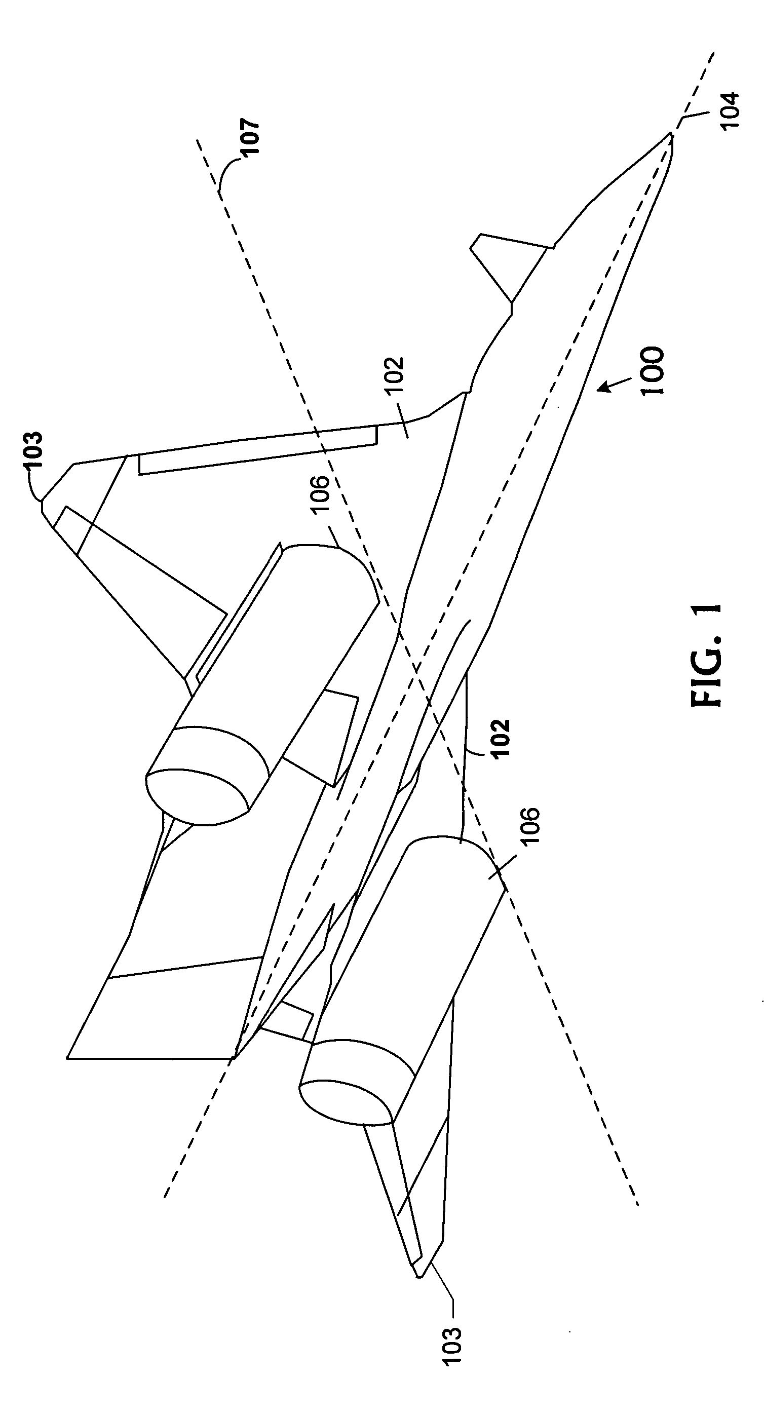
[0035]FIG. 1 illustrates an example of an aircraft 100 having a longitudinal axis 104 forward and aft to which an airfoil is coupled. Airfoils are generally designed to maximize aerodynamic performance at a particular Mach number or range of Mach numbers. In various circumstances and conditions, operation at off-design Mach numbers is desirable. The airfoil includes aircraft wings 102. However, the airfoil may also include other aerodynamic shapes including the fuselage, tail, and other structures within the air stream. Wings 102 further include winglets 103.

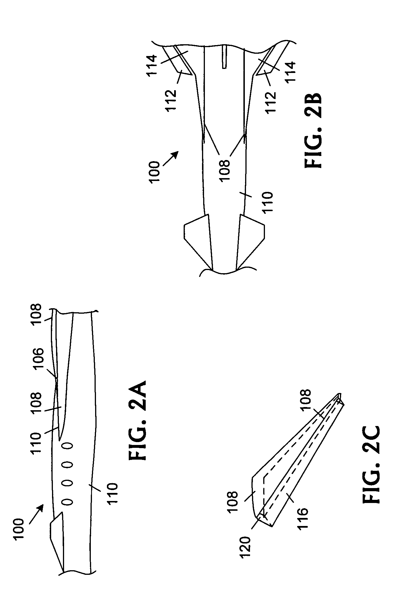
[0036]FIGS. 2A, 2B, and 2C illustrate side, top, and three-dimensional perspective views of an embodiment of portions of wings for usage on aircraft 100. Wings 102 couple to a strake 108 that couples to aircraft fuselage 110 and extends along a portion o...


PUM


Abstract

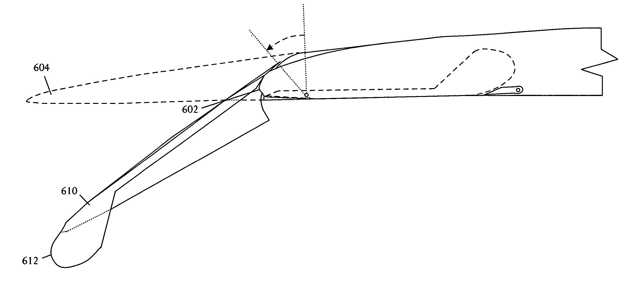
A wing for use on a supersonic aircraft that includes an inboard section a central section of the wing outboard of the inboard portion, and an outboard section. The outboard section can be a winglet oriented anhedrally relative to a lateral axis of the supersonic aircraft. Leading edge segments on the inboard section, central section and outboard winglet may have mounted thereon leading-edge flaps. These flaps are adjusted by a control system operable to reposition the leading-edge flaps in order to improve the aerodynamic performance of the supersonic aircraft. This winglet promotes sonic boom minimization. Further, the wing tip anhedral allows greater inboard dihedral. This effectively pushes lift aft for sonic boom and control purposes while minimizing the movement of control surfaces.

Description


Claims


Application Information

Patent Timeline
Owner SUPERSONIC AEROSPACE INT
Learn More