
Disc brake

a disc brake and disc technology, applied in the direction of fluid actuated brakes, axially engaging brakes, mechanical devices, etc., can solve the problems of reducing production efficiency and cumbersome operation of forming the passage opening, and achieve the effects of high production efficiency, easy formation, and high degree of design freedom

Inactive Publication Date: 2005-06-02
HITACHI LTD
View PDF3 Cites 14 Cited by
  • Summary
  • Abstract
  • Description
  • Claims
  • Application Information

AI Technical Summary

Benefits of technology

[0004] Therefore, it is an object of the present invention to provide a disc brake in which an opening for forming a brake fluid passage can be easily formed, thus achieving high production efficiency, and which enables the position of the opening for the brake fluid passage to be determined with a high degree of freedom of design.

Problems solved by technology

Therefore, the passage opening must be formed with high machining accuracy, and an operation for forming the passage opening becomes cumbersome.
This lowers production efficiency.
Further, since the passage opening must be formed while avoiding interference with the open end of the bore, a degree of freedom of design when determining the position of the passage opening is low.

Method used


Image

  • Disc brake
  • Disc brake
  • Disc brake

Examples


Embodiment Construction

[0036] Hereinbelow, embodiments of the present invention are described, referring to the drawings.

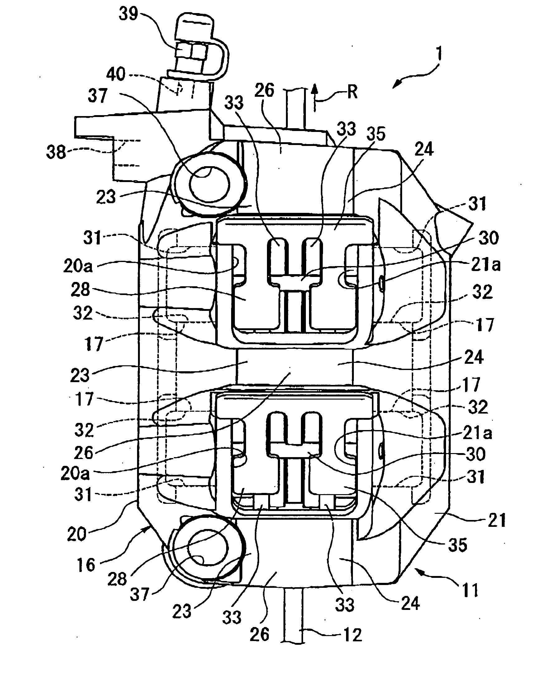
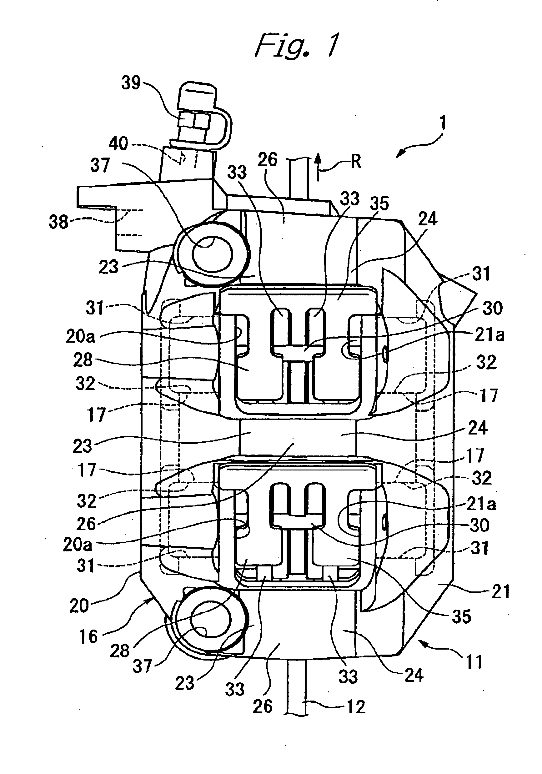
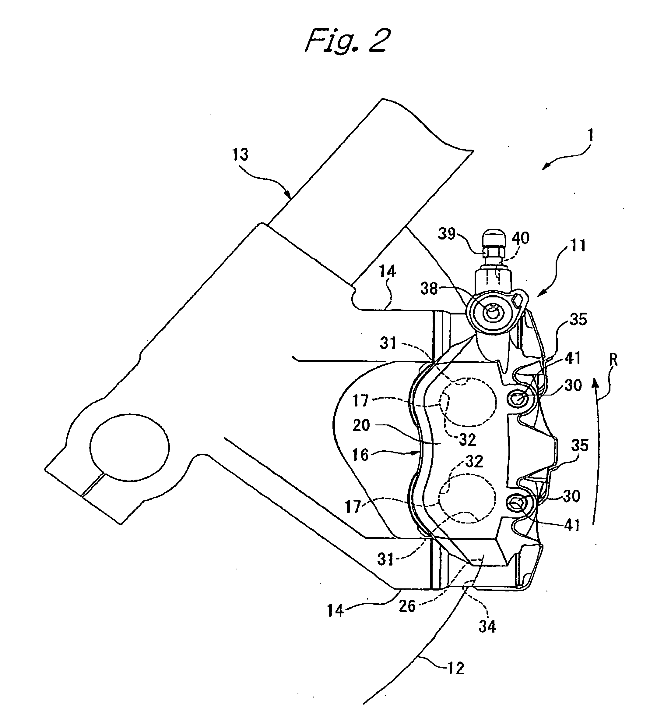
[0037] In FIGS. 1 and 2, reference numeral 1 denotes an opposed-piston type disc brake. A caliper 11 of this disc brake is an opposed-piston type caliper 11. The caliper 11 comprises a caliper body 16 which extends over a disc 12, as shown in FIG. 1, and which is mounted on a mount portion 14 of a front fork 13 as a non-rotational portion of a body of a vehicle (a motor cycle in this embodiment), as shown in FIG. 2. The caliper 11 further comprises a plurality of pairs (two pairs in this embodiment) of pistons 17 slidably provided in the caliper body 16, so as to face each other with the disc 12 being disposed therebetween. In the following description, a radial direction of the disc 12, an axial direction of the disc 12, a direction of rotation of the disc 12 refer to those in a state in which the caliper body is mounted on a vehicle body. In FIGS. 1 and 2, an arrow R indicates the di...


PUM

PropertyMeasurementUnit
diameteraaaaaaaaaa
circumferenceaaaaaaaaaa
gravityaaaaaaaaaa

Abstract

In a disc brake, a pair of pads are disposed on opposite sides of a disc. A caliper body extends over the disc. A piston is slidably held in the caliper body on a side opposite to the disc relative to the corresponding pad. In the caliper body, a prepared hole for a bore into which the piston is slidably fitted and a recess extending from a bottom portion of the prepared hole outwardly in a radial direction of the prepared hole are formed by means of a core during casting. A linear passage opening is formed by cutting from an exterior surface of the caliper body so as to communicate with the recess. In this disc brake, an opening for forming a brake fluid passage can be easily formed by machining, resulting in high production efficiency. The position of the opening can be determined with a high degree of freedom of design.

Description

BACKGROUND OF THE INVENTION [0001] The present invention relates to a disc brake for a vehicle. [0002] In a disc brake for a vehicle, a pair of pads are disposed on opposite sides of a disc, and pistons, each of which is disposed on a side opposite to the disc relative to the corresponding pad, are adapted to press the pads against the disc, to thereby apply a braking force to the vehicle. The pistons are slidably fitted into bores formed in a caliper body. In a disc brake of this type disclosed in U.S. Pat. No. 6,367,595, a bottom portion of each of the bores for the pistons is formed by a member externally attached to an open end of the bore. Before the open end of the bore is closed by this bottom portion, a tool is inserted from the open end of the bore, and a passage opening is formed by cutting from a portion in the bore on a side of the bottom portion thereof, and then the bore is closed by threadably engaging the bottom portion with the caliper body. [0003] In the above-ment...

Claims


Application Information

Patent Timeline
Patent Type & Authority Applications(United States)
IPC IPC(8): F16D55/224F16D55/00F16D55/228F16D65/02
CPCF16D55/228F16D2055/0016Y10T29/49989F16D2055/0091F16D2250/0007F16D2055/002
Inventor NANRI, KEISUKE
Owner HITACHI LTD
Learn More