Anti-slip attachment for ladders
a technology of anti-slip attachment and ladder, which is applied in the direction of scaffold accessories, construction, building aids, etc., can solve the problems of extending ladders, affecting the safety of workers, and causing injuries and deaths, and achieves the effect of high surface friction coefficien
- Summary
- Abstract
- Description
- Claims
- Application Information
AI Technical Summary
Benefits of technology
Problems solved by technology
Method used
Image
Examples
second embodiment
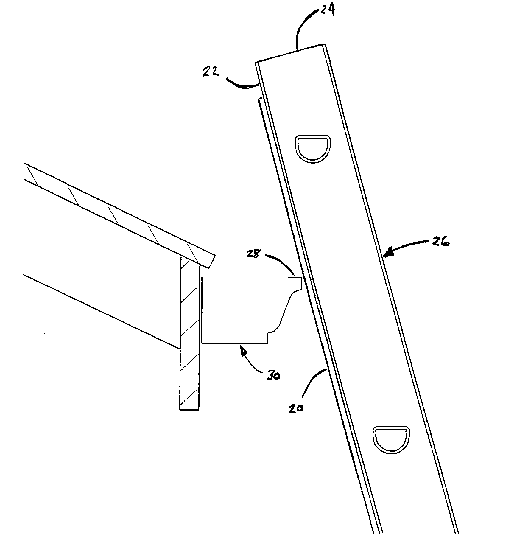
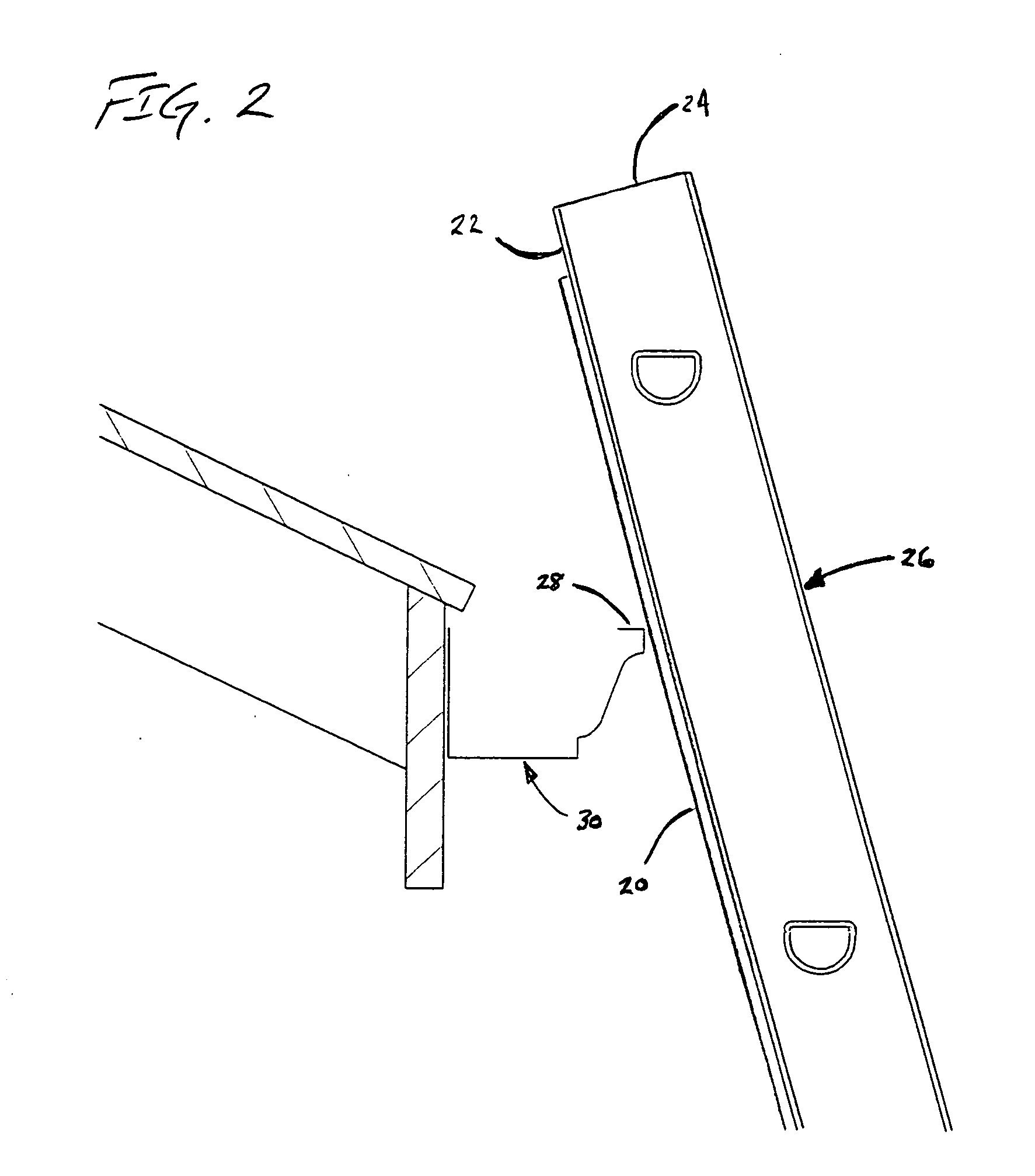
[0042] In the second embodiment, which is illustrated in FIGS. 5-7, there are first and second clips, 50a, 50b that attach to the two rails 52a, 52b of the ladder and which engage the lip 28 of the gutter 30 in substantially the same manner as described above. The clips consequently provide separate frames on which the tape is mounted, which are in turn mountable to the ladder.
[0043] As can be seen in FIG. 7, each of the clips is formed in the shape of semi-enclosed channel. In the illustrated embodiment the channel is constructed of steel-sheet metal, however, it will be understood that plastic or other suitable materials may be used. The channel includes a comparatively wide web 54 having a flange 56 along its forward edge, the strip of foam material 58 being adhered to the outer surface thereof. A second flange 58 along the opposite edge of the web 54 is bent back parallel to the web so as to form a return 60 that defines semi enclosed U-shaped channel area 26. The inside angle b...
third embodiment
[0045] In a third embodiment, which is illustrated in FIGS. 8-12, there are two channel-shaped frames 70a, 70b (only 70a being visible in FIG. 8), that have a channel-shaped configuration and that slip over the two side rails 72a, 72b of the ladder rather than clipping onto them in the manner shown in FIGS. 5-7.
[0046] As can be seen in FIG. 9, each of the slip-on frames has a generally channel-shaped configuration, with a side web 74 and forward and rearward flanges 76, 78 with returns 80, 82, that in combination define a semi-enclosed, U-shaped channel area 84; the generally U-shaped configuration facilitates manufacture of the frames from stamped / bent sheet metal, however, it will be understood that in some embodiments that the channel areas may be fully enclosed. A strip 86 of the resiliently compressible material is mounted to the forwardly-directed face of each forward flange 76, in a manner similar to the embodiment described with regard to FIGS. 5-7. However, at the upper and...
fourth embodiment
[0050]FIG. 13 shows the invention, in which the frames 120a, 120b have a somewhat simplified configuration, with the forward and rearward flanges 122, 124 extending at right angles to the webs 126. As with the embodiments described above, the strips of resiliently compressible cushioning material 128 are adhered to the outer surfaces of the forward flanges 122. In this embodiment, however, mounting is accomplished by means of a threaded rod 130 that passes through a hollow interior of one of the staves 132 of the ladder; conventionally, the staves of aluminum ladders are hollow and open at each end so that the rod can be readily passed therethrough. First and second wing nuts 134 are mounted on the ends of the rod 130 and secure the clips to the rails of the ladder when tightened; suitably, the rod is a 20-inch length of ¼-inch ready rod, with ¼-inch wing nuts on each end. However, it will be understood that in some embodiments a nut may be used on only one end of the rod, with the ...
PUM
 Abstract
Description
Claims
Application Information
 - R&D
- Intellectual Property
- Life Sciences
- Materials
- Tech Scout
- Unparalleled Data Quality
- Higher Quality Content
- 60% Fewer Hallucinations
Browse by: Latest US Patents, China's latest patents, Technical Efficacy Thesaurus, Application Domain, Technology Topic, Popular Technical Reports.
© 2025 PatSnap. All rights reserved.Legal|Privacy policy|Modern Slavery Act Transparency Statement|Sitemap|About US| Contact US: help@patsnap.com


