
Method and system for de-interlacing digital images, and computer program product therefor

a digital image and interlacing technology, applied in the field of digital image processing, can solve the problems of unpleasant “mosaic” effect, de-interlacing procedures listed above, and inconvenient operation, and achieve the effect of optimizing operation performan

Active Publication Date: 2005-05-26
STMICROELECTRONICS SRL
View PDF30 Cites 10 Cited by
  • Summary
  • Abstract
  • Description
  • Claims
  • Application Information

AI Technical Summary

Benefits of technology

[0022] One embodiment of the present invention provides a solution that guarantees optimal performance in the operations of de-interlacing of an interlaced digital image.
[0024] Basically, the solution described herein provides for making a choice between different procedures for de-interlacing digital images that generate different reconstructions, by an operation of evaluation and minimization of a cost function. There are also proposed improved procedures of digital image de-interlacing of a spatial and temporal type.
[0025] As compared to the known solutions, a solution proposed herein enables a reconstruction to be obtained without appreciable visual defects.

Problems solved by technology

The PAL system was originally conceived for systems with cathode-ray displays, but television images are not suited for being displayed on other types of display, such as, for example computer monitors, or modern televisions with plasma or liquid-crystal displays.
A television video sequence in PAL format, displayed on these systems, would cause an unpleasant “mosaic” effect, due to the fact that each image is in effect made up of two different interlaced fields.
The de-interlacing procedures listed above, however, do not succeed in guaranteeing optimal performance in ail the situations that can occur during processing of a video sequence.

Method used


Image

  • Method and system for de-interlacing digital images, and computer program product therefor
  • Method and system for de-interlacing digital images, and computer program product therefor
  • Method and system for de-interlacing digital images, and computer program product therefor

Examples


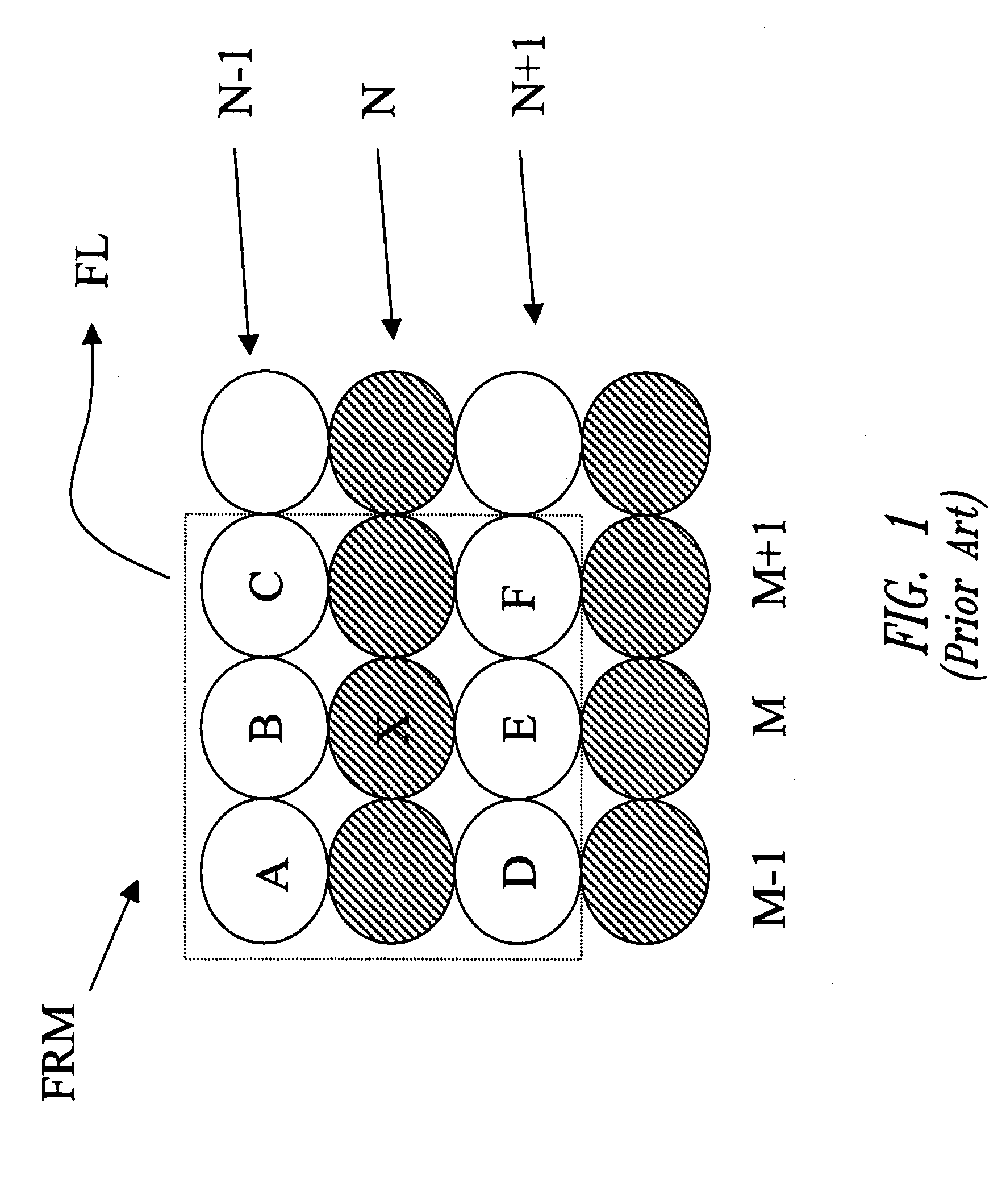
Embodiment Construction

[0033] The de-interlacing procedure proposed provides basically for providing a non-motion-compensated (or spatial) de-interlacing procedure as well as a motion-compensated (or temporal) de-interlacing procedure designed to produce reconstructions of improved quality, as well as making a decision among the reconstructions originated by said spatial and temporal procedures, introducing an appropriate cost function for making this decision.

[0034] There is thus described hereinafter, first of all, a non-motion-compensated digital-image de-interlacing procedure which improves the non-motion-compensated procedure for de-interlacing digital images of the ELA type described previously with reference to FIG. 1 by introducing the following operations: [0035] an operation of extension of the work window; [0036] operations designed to obtain a sub-pixel degree of precision; [0037] an operation of adaptive sizing of the work window; and [0038] an operation of post-processing and final filterin...


PUM


Abstract

To carry out de-interlacing of digital images there is provided a spatial-type de-interlacing process to be applied to a digital image for obtaining a spatial reconstruction. Furthermore, to the digital image there are also applied one or more temporal-type de-interlacing processes for obtaining one or more temporal reconstructions, and the spatial reconstruction and the one or more temporal reconstructions are sent to a decision module. The decision module applies a cost function to the spatial reconstruction and the temporal reconstructions and chooses from among the spatial reconstruction and the temporal reconstructions the one that minimizes the cost function. Preferential application is to display systems, in particular displays of a cathode-ray type, liquid-crystal type, and plasma type which use a mechanism of progressive scan.

Description

BACKGROUND OF THE INVENTION [0001] 1. Field of the Invention [0002] The present invention relates to techniques for digital-image processing, and has been developed with particular attention paid to its possible application to the processing of television images and to the display of the television signal on displays, such as personal-computer displays of the cathode-ray type, liquid-crystal type or plasma type, which use a progressive-scanning mechanism. [0003] Even though in what follows, for reasons of clarity and simplicity of exposition, practically exclusive reference will be made to this application, it must in any case be borne in mind that the significance of application of the invention is more general. The invention is in fact applicable to all techniques of digital-image processing in which there arise operating conditions of the type described in what follows. [0004] 2. Description of the Related Art [0005] The television system adopted in Europe, i.e., the Phase-Altern...

Claims


Application Information

Patent Timeline
Patent Type & Authority Applications(United States)
IPC IPC(8): H04N5/44H04N7/01
CPCH04N7/012H04N7/0142H04N7/014
Inventor ALFONSO, DANIELEPAU, DANILOPRIVITERA, ELIOSCHIAVONE, ANGELO
Owner STMICROELECTRONICS SRL
Learn More