
Source liquid supply apparatus having a cleaning function

Active Publication Date: 2005-05-26
LAIR LIQUIDE SA POUR LETUDE & LEXPLOITATION DES PROCEDES GEORGES CLAUDE
View PDF14 Cites 18 Cited by
  • Summary
  • Abstract
  • Description
  • Claims
  • Application Information

AI Technical Summary

Benefits of technology

[0118] As has been explained in the preceding, this invention provides a source liquid supply apparatus that incorporates a cleaning function and that avoids leaving source liquid- and / or cleaning fluid-derived residues in the vicinity of the joint or connection region between the source liquid feed conduit and the source tank. This invention also provides a method for detaching the source tank from the foregoing apparatus and a method for cleaning the source liquid feed conduit

Problems solved by technology

The equipment used to fabricate semiconductor devices and electronic devices and instruments frequently employs source liquids in the form of difficult-to-handle chemical reagents whose residues are difficult to remove simply by a gas purge.
Once such a source liquid has passed through, for example, a manifold or vaporizer, the interior thereof cannot be satisfactorily treated by purging and cleaning with just a simple gas purge cycle (repetitive pressurization with gas and vacuum exhaust) when it is desired to carry out maintenance or exchange or alter the reagent.
When such a vaporizer is used in a CVD system, by-products are produced in the vaporizer section from the source reagent, which causes clogging and lowers the vaporizing efficiency.
A problem common to the type of prior art systems under consideration, including the systems taught in the United States patents listed above, is the presence of a difficult-to-purge dead space in the vicinity of the joint or connection between the source tank and the conduit for feeding source liquid to the process apparatus.
When, for example, these residues come into contact with air when the source tank is exchanged, they form difficult-to-remove substances that clog the piping or produce substances that poison the process.

Method used


Image

  • Source liquid supply apparatus having a cleaning function
  • Source liquid supply apparatus having a cleaning function
  • Source liquid supply apparatus having a cleaning function

Examples


Embodiment Construction

[0050] Embodiments of this invention are explained below with reference to the drawings. In the description that follows, constituent elements that have approximately the same structure and function are assigned the same reference symbol and their description will be repeated only when necessary.

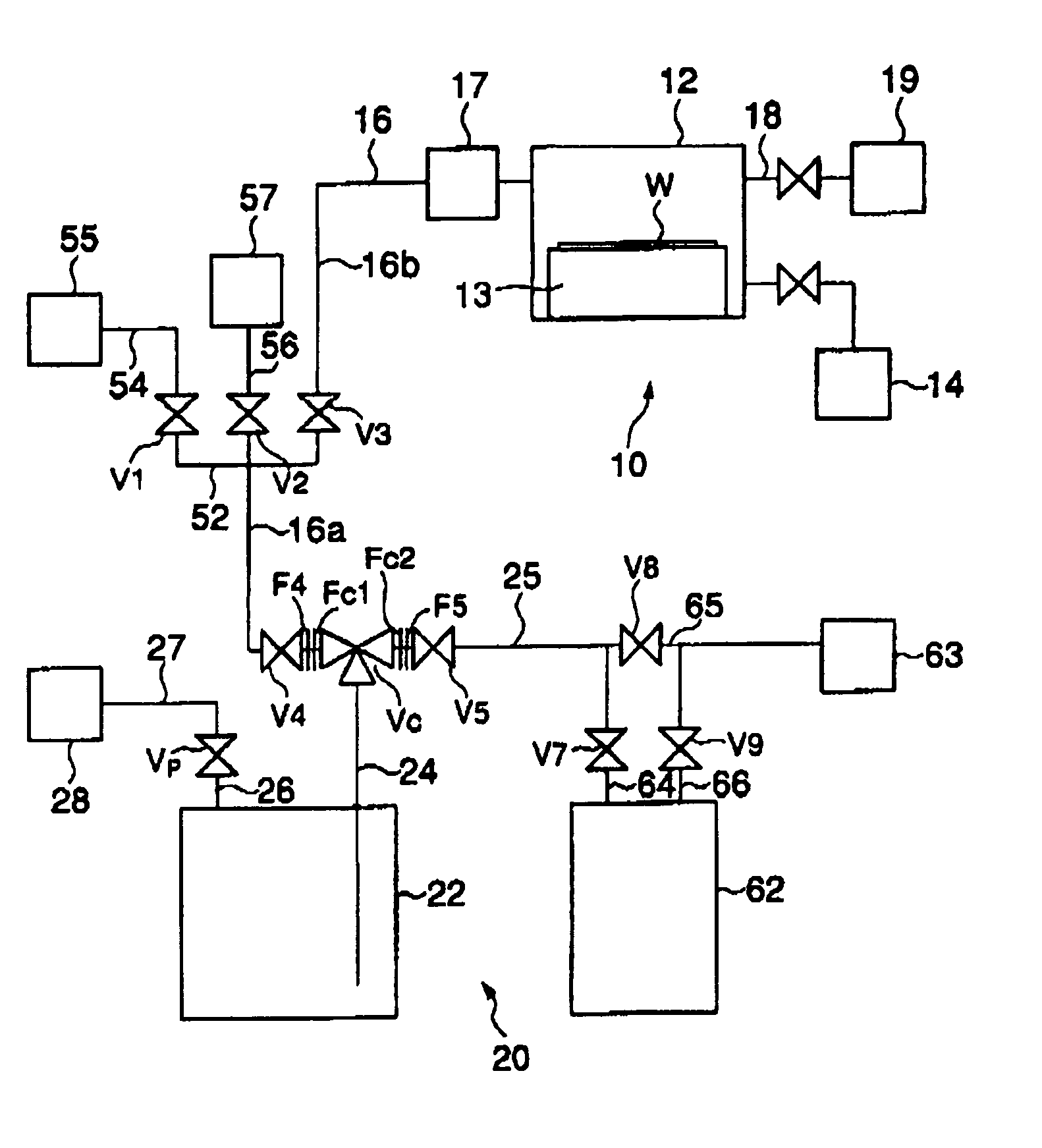
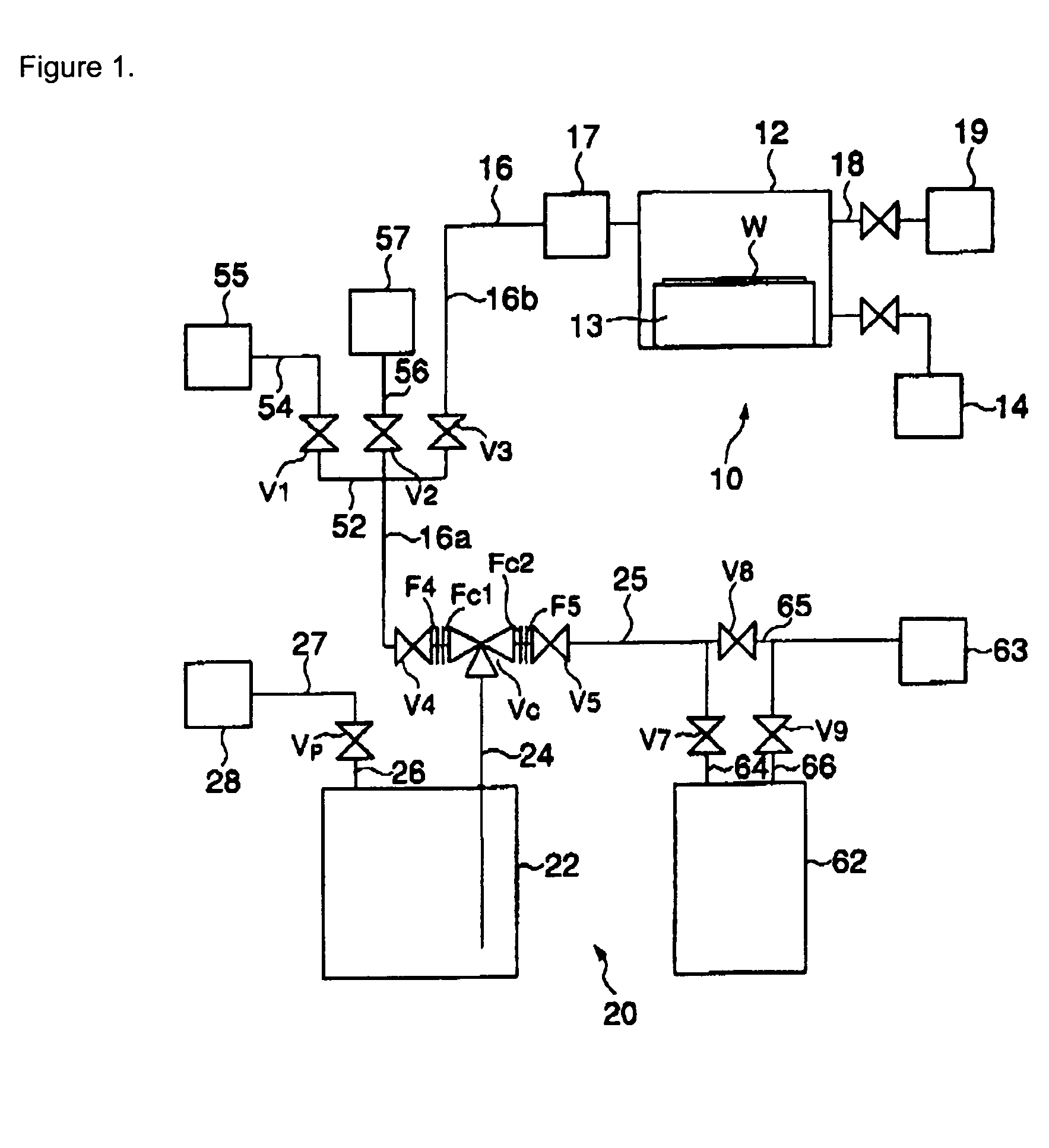
[0051]FIG. 1 contains a schematic drawing of the conduit layout in an MOCVD system that produces tantalum oxide (Ta2O5) film. This MOCVD system incorporates a source liquid supply apparatus that is an embodiment of this invention. More specifically, this system is provided with an MOCVD apparatus 10 and a source liquid supply apparatus 20.

[0052] The MOCVD apparatus 10 contains a leaktight process compartment 12, in the interior of which is disposed a susceptor 13 that can hold, support, and heat a semiconductor wafer W. The process compartment 12 is connected to a vacuum exhaust member 14 that can exhaust the interior of the process compartment 12 and can establish a vacuum therein. The pr...


PUM

PropertyMeasurementUnit
Pressureaaaaaaaaaa
Pressureaaaaaaaaaa

Abstract

(Problem) To provide a source liquid supply apparatus that avoids leaving source liquid- and / or cleaning fluid-derived residues in the vicinity of the joint or connection region between the source liquid feed conduit and the source tank. (Solution) A flow-switching mechanism Vc is attached to the source tank 22 of a source liquid supply apparatus 20. This flow-switching mechanism Vc has a first port 33 that is connected to the discharge port conduit 24 of the source tank 22, a second port 34 that is connected to a feed conduit 16, and a third port 35 that is connected to an exhaust conduit 25. The first port 33 can be closed by a valve member 43 on a diaphragm 42 disposed within a common compartment 38 while communication is maintained between the second and third ports 34 and 35. A cleaning fluid source 55 and a purge gas source 57 are connected to the feed conduit 16. Purge gas and cleaning fluid fed into the feed conduit 16 are discharged from the second and third ports 34 and 35 through the exhaust conduit 25.

Description

[0001] This invention relates to a source liquid supply apparatus having a cleaning function, to a method for detaching the source tank from said supply apparatus, and to a method for cleaning a source liquid feed conduit. More particularly, this invention relates to the structure of an apparatus for supplying a source liquid, such as a chemical reagent, to a particular facility, for example, to a metalorganic chemical vapor deposition (MOCVD) apparatus. The invention additionally relates to a maintenance technology for said supply apparatus. DESCRIPTION OF THE PRIOR ART [0002] The equipment used to fabricate semiconductor devices and electronic devices and instruments frequently employs source liquids in the form of difficult-to-handle chemical reagents whose residues are difficult to remove simply by a gas purge. Once such a source liquid has passed through, for example, a manifold or vaporizer, the interior thereof cannot be satisfactorily treated by purging and cleaning with jus...

Claims


Application Information

Patent Timeline
IPC IPC(8): B08B9/00B08B9/02C23C16/44
CPCB08B9/00C23C16/45561C23C16/4402B08B9/032B08B9/027C23C16/56
Inventor LETESSIER, OLIVIERKIMURA, MASAOGIRARD, JEAN-MARCNASU, AKINOBU
Owner LAIR LIQUIDE SA POUR LETUDE & LEXPLOITATION DES PROCEDES GEORGES CLAUDE
Learn More