
Tearable retention apparatus and method for an airbag cushion

Inactive Publication Date: 2005-05-19
AUTOLIV ASP INC
View PDF8 Cites 50 Cited by
  • Summary
  • Abstract
  • Description
  • Claims
  • Application Information

AI Technical Summary

Benefits of technology

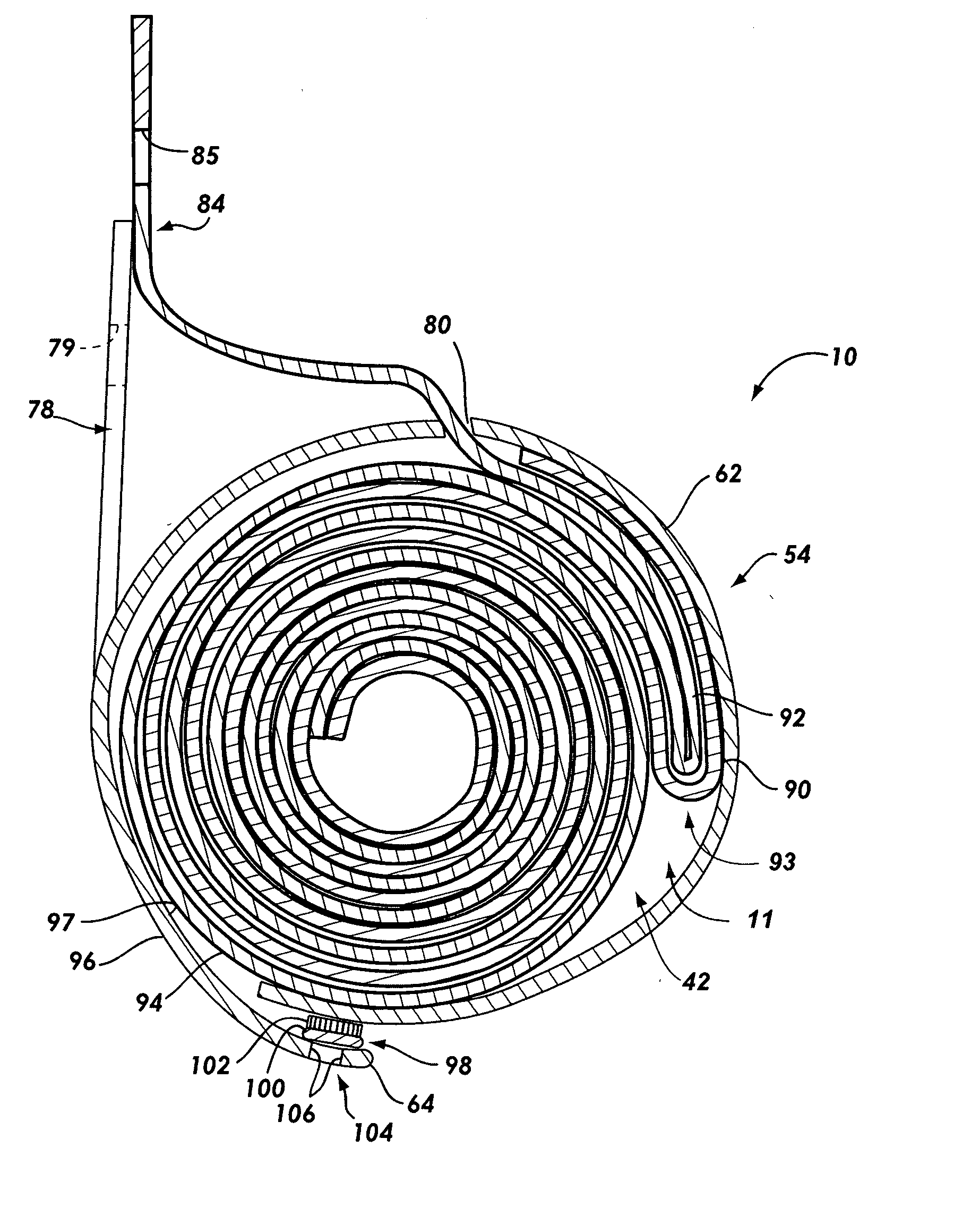
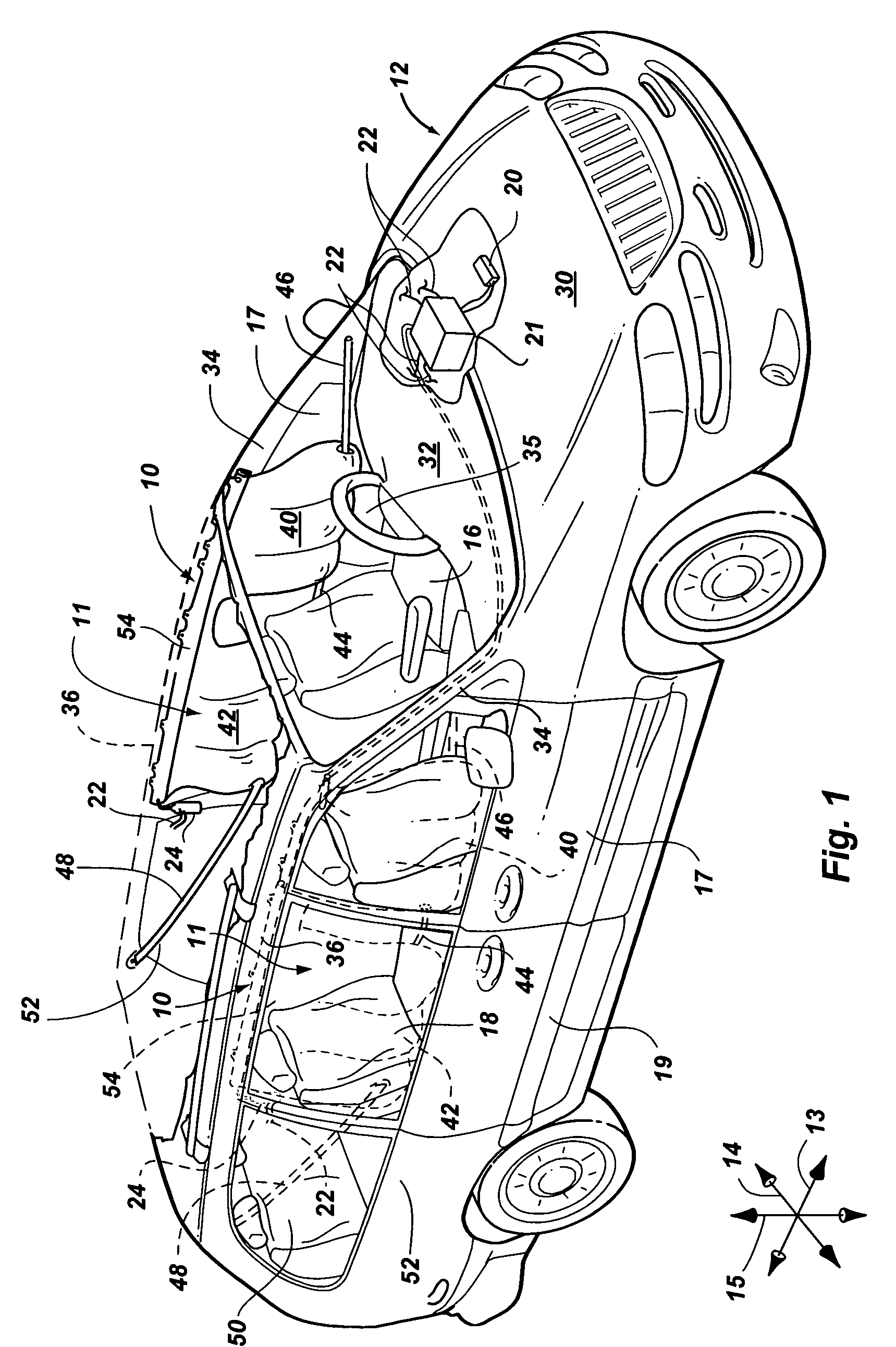
[0018] In operation, a collision is detected and the ECU transmits an activation signal to the inflator. The activation signal causes the inflator to deploy, thereby producing inflation gas. The inflation gas is conducted through the gas guide into the cushion. The cushion begins to expand and the resulting outward pressure on the flexible member causes the thread of the sewn seam to break, thereby permitting the hook-and-loop fastening strip to separate from the non-napped side of the flexible member. The hook-and-loop fastening strip remains fastened to the napped side of the flexible member. The cushion inflates through the resulting opening of the flexible member, and extends alongside the lateral surface of the vehicle to provide lateral impact protection.
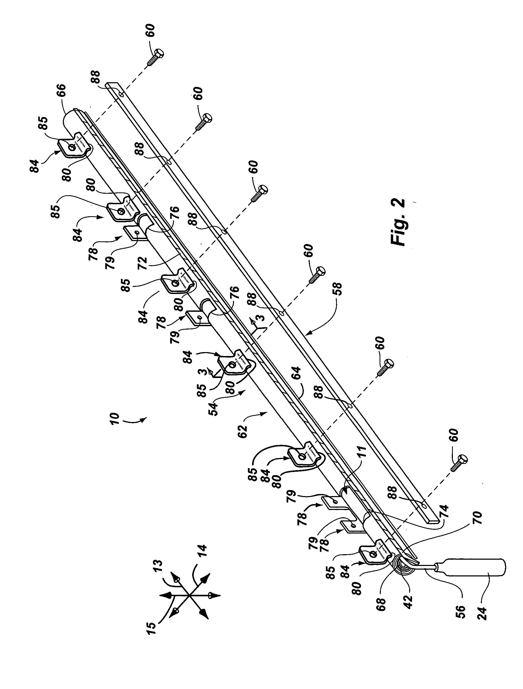
[0020] More precisely, each base plate is attached to the corresponding flexible member via an attachment mechanism in the form of an adhesive. Each hook is insertable through a hole formed proximate the second edge of the corresponding flexible member. The adhesive has an attachment strength selected to permit removal of the base plate from the flexible member in response to expansion of the cushion. The hooks may remain retained by the corresponding holes. Detachment of the base plates from the flexible members permits the flexible members to open so that the cushion can inflate.
[0023] According to another alternative embodiment of the invention, an inflatable curtain module has a cushion similar to that described above. The cushion is kept in the stowed configuration by multiple retention apparatus, each of which includes a flexible member configured as a strap. Each of the flexible members has a first edge and a second edge. The flexible members are attached to the cushion proximate each of the first and second edges. The first and second edges are disposed on either side of the outwardly disposed edge of the rolled cushion so that the retention apparatus are able to keep the cushion in the stowed configuration.
[0027] Through the use of airbag modules and associated methods of the present invention, airbag cushions may be inexpensively and securely retained in the stowed configuration in a manner that permits reliable deployment. These and other features and advantages of the present invention will become more fully apparent from the following description and appended claims, or may be learned by the practice of the invention as set forth hereinafter.

Problems solved by technology

Unfortunately, such perforations must generally be formed with considerable precision to ensure that the wrap is strong enough to remain intact during further fabrication, shipping, and installation, and yet weak enough at the perforation to permit the wrap tear during deployment.
If the wrap does not tear properly along the perforation during deployment, the cushion may fail to inflate in the proper manner.
As a result, the tolerances of the perforations tend to be relatively tight, and the perforations are difficult to form with economical techniques.
Furthermore, many known wrap designs are difficult to place around the cushion.
Some wraps, particularly those designed for elongated cushions such as inflatable curtain cushions, present assembly challenges because the cushion must be inserted lengthwise into the wrap.
In some instances, relatively elaborate or labor intensive methods must be used to align the cushion with the wrap and then pull the cushion into the wrap.
Some wraps can be improperly assembled with the corresponding cushion.
The time required to form a perforated wrap and place the wrap around the cushion adds significantly to the time required to produce the airbag module.
Furthermore, such challenges and / or disadvantages also add to the cost of the module, thereby decreasing the availability and use of such airbag modules.

Method used


Image

  • Tearable retention apparatus and method for an airbag cushion
  • Tearable retention apparatus and method for an airbag cushion
  • Tearable retention apparatus and method for an airbag cushion

Examples


Embodiment Construction

[0035] The presently preferred embodiments of the present invention will be best understood by reference to the drawings, wherein like parts are designated by like numerals throughout. It will be readily understood that the components of the present invention, as generally described and illustrated in the figures herein, could be arranged and designed in a wide variety of different configurations. Thus, the following more detailed description of the embodiments of the apparatus, system, and method of the present invention, as represented in FIGS. 1 through 6, is not intended to limit the scope of the invention, as claimed, but is merely representative of presently preferred embodiments of the invention.

[0036] For this application, the phrases “connected to,”“coupled to,” and “in communication with” refer to any form of interaction between two or more entities, including mechanical, electrical, magnetic, electromagnetic, and thermal interaction. The phrase “attached to” refers to a ...


PUM


Abstract

An airbag module may include an inflator, a cushion, and a retention apparatus that keeps the cushion in a stowed configuration until deployment. The retention apparatus may include a flexible member wrapped around the cushion and a hook-and-loop fastening strip attached to the flexible member via a sewn seam. The hook-and-loop fastening strip has hooks fastened to the flexible member to secure the flexible member around the cushion. The sewn seam is weak enough to permit the hook-and-loop fastening strip to break away from the flexible member. When the cushion begins to inflate, the sewn seam breaks to allow the hook-and-loop fastening strip to separate from one side of the flexible member while remaining attached to the opposite side. The cushion is able to inflate through the corresponding opening formed in the retention apparatus. In alternative embodiments, the flexible member, fastener, and attachment mechanism may be reconfigured or omitted.

Description

BACKGROUND OF THE INVENTION [0001] 1. Field of the Invention [0002] The present invention relates to systems and methods for protecting vehicle occupants from injury. More specifically, the present invention relates to a retention apparatus for keeping an airbag cushion in a stowed configuration until deployment. [0003] 2. Description of Related Art [0004] The inclusion of inflatable safety restraint devices, or airbags, is now a legal requirement for many new vehicles. Airbags are typically installed in the steering wheel and in the dashboard on the passenger side of a car. Additionally, airbags may be installed to inflate beside the passenger to provide side impact protection, in front of the knees to protect the knees from impact, or at other strategic locations. [0005] In the event of an accident, a sensor system within the vehicle senses an impact situation and triggers the ignition of an inflator. Inflation gases from the inflator fill the airbag cushions, which immediately in...

Claims


Application Information

Patent Timeline
IPC IPC(8): B60R21/20B60R21/213
CPCB60R21/213B60R21/201
Inventor HENDERSON, DAVIDLIGHTHALL, BRIAN A.
Owner AUTOLIV ASP INC
Learn More