
Fastening member and siding boards attachment structure using the fastening member

Inactive Publication Date: 2005-05-19
NICHIHA CORP
View PDF8 Cites 40 Cited by
  • Summary
  • Abstract
  • Description
  • Claims
  • Application Information

AI Technical Summary

Benefits of technology

[0007] In the fastening member 50 shown in FIG. 6, since the locking portion 52 is formed by laminating the steel sheet two fold, the fastening member is rather heavy and requires much steel, resulting in higher cost.
[0008] In the fastening member 70 shown in FIG. 7, the locking portion 73 is formed of a single sheet and is therefore less heavy and less costly. However, since the locking portion 73 is extended from the substrate portion 71 that is the mount portion on the building frame, the locking portion 73 of the fastening member 70 is longer than the locking portion 52 of the fastening member 50 shown in FIG. 6, in which the locking portion 52 is extended from the support portion 51. Thus, the strength of the locking portion 73 is rather unreliable, particularly when a heavy, large-sized board is to be fastened.

Problems solved by technology

In the fastening member 50 shown in FIG. 6, since the locking portion 52 is formed by laminating the steel sheet two fold, the fastening member is rather heavy and requires much steel, resulting in higher cost.
Thus, the strength of the locking portion 73 is rather unreliable, particularly when a heavy, large-sized board is to be fastened.
Thus, when the adjacent portions of two laterally adjacent boards are to be fastened with a single fastening member 70, the back surface of each board must be supported by one of the two, i.e., left and right, support portions 72, resulting in a fastening stability problem.

Method used


Image

  • Fastening member and siding boards attachment structure using the fastening member
  • Fastening member and siding boards attachment structure using the fastening member
  • Fastening member and siding boards attachment structure using the fastening member

Examples


Embodiment Construction

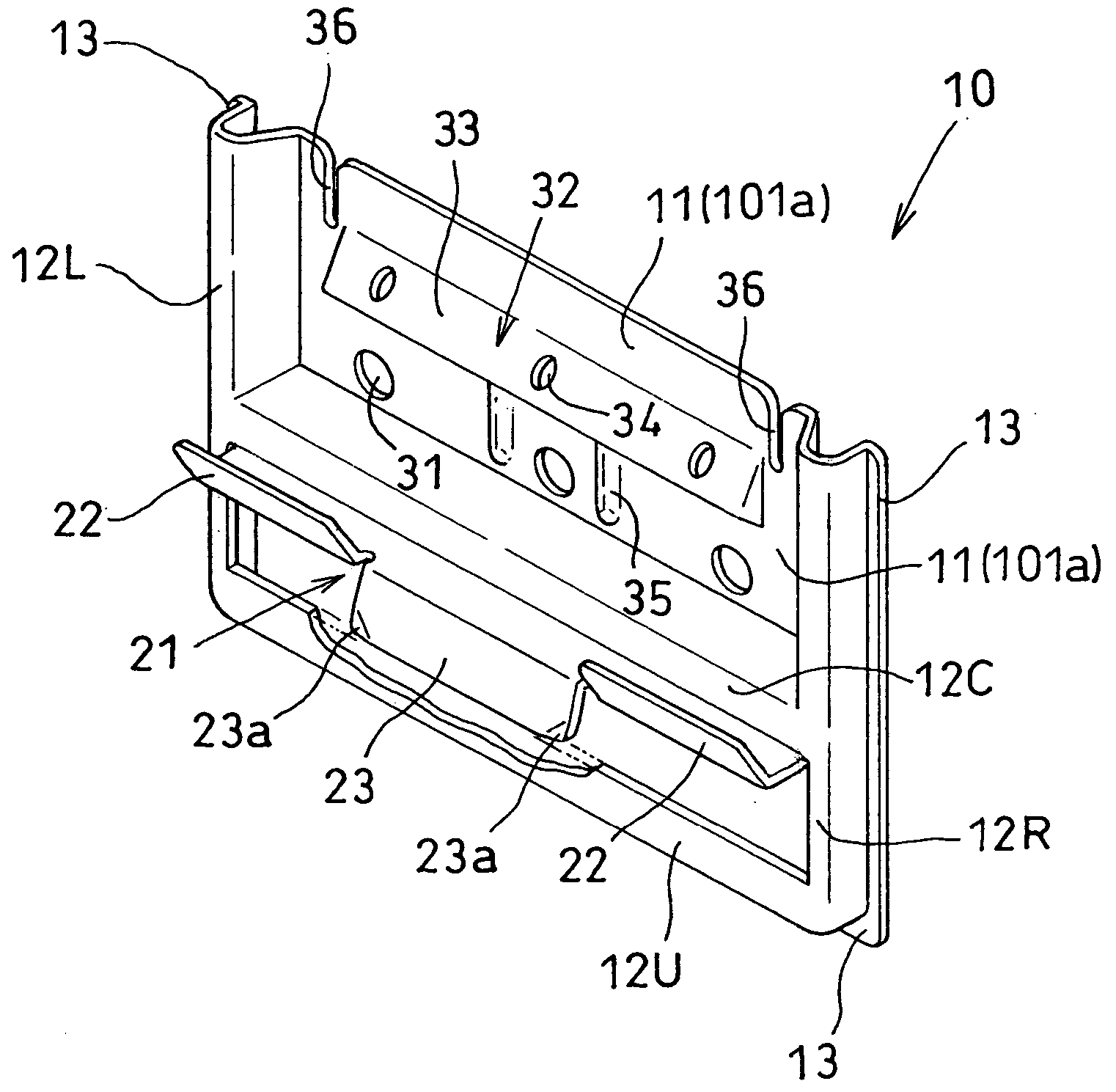
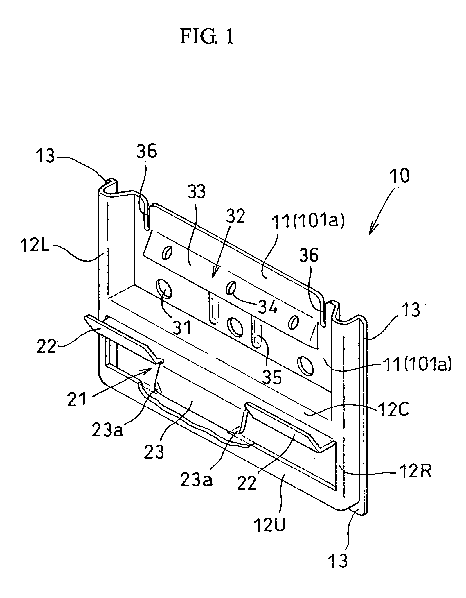
[0034] With reference to the drawings, a fastening member according to an embodiment of the invention and siding boards attachment structure utilizing the fastening member are described. FIG. 1 is a perspective view of the embodiment of the fastening member of the invention. FIG. 3 is a perspective view of the exterior wall structure utilizing the fastening member.

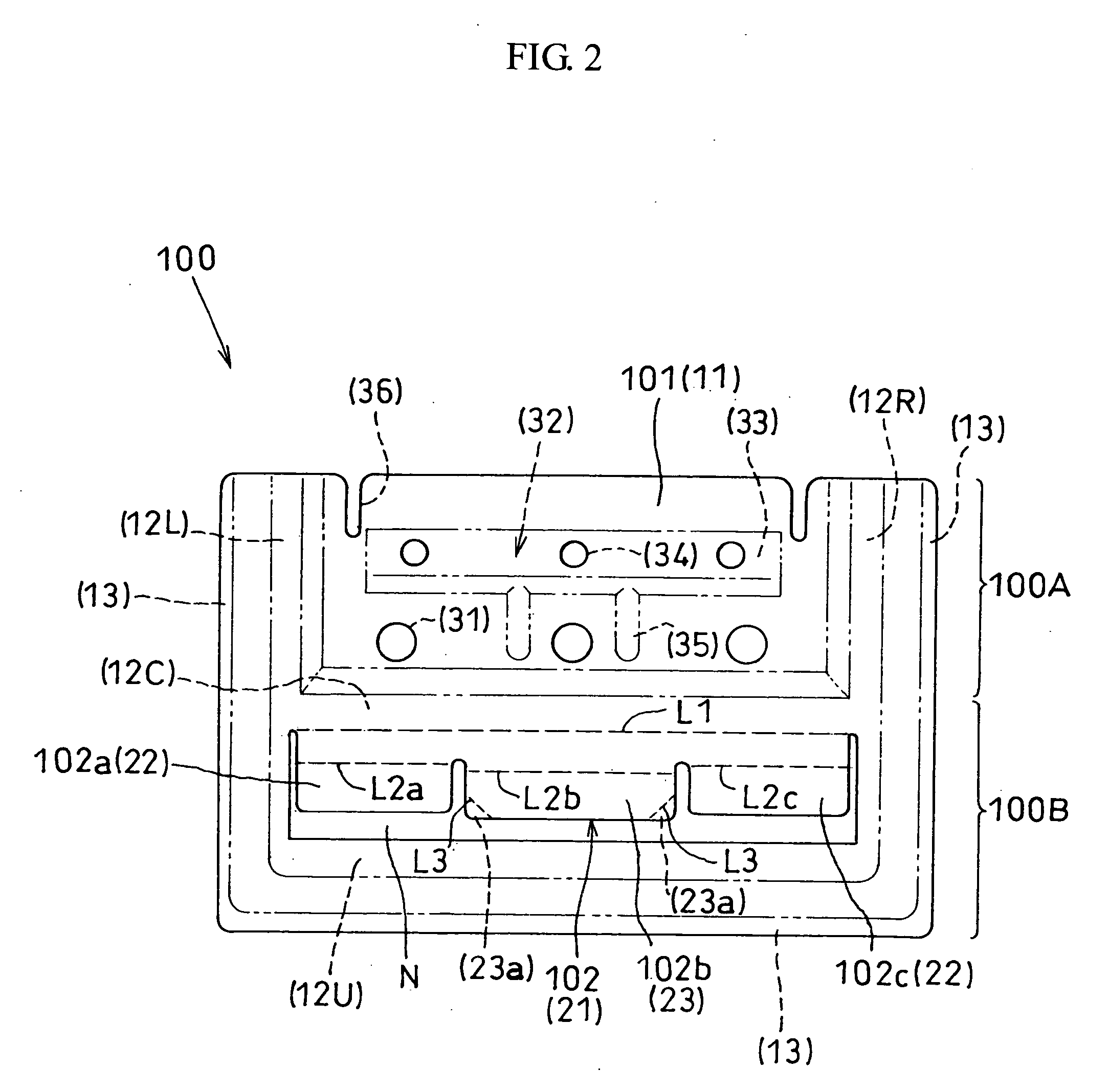
[0035] A fastening member 10 shown includes a left-side supporting portion 12L and a right-side supporting portion 12R on the sides thereof that will abut on the back surface of an exterior wall when fastened. The fastening member 10 also includes, in the intermediate region between the left- and right-side portions 12L and 12R, a substrate portion 11 that is to be fixed to a building frame. Below the substrate portion 11, the intermediate region includes a central support portion 12C that will abut on the back surface of a board when fastened. Further below, there are a locking portion 21 to be locked on the upper and lo...


PUM


Abstract

A fastening member 10 produced from a single steel sheet that is capable of stably supporting an exterior wall board and ensuring ventilation between the board and a building frame. The fastening member 10 comprises a left-side support portion 12L and a right-side support portion 12R on either side thereof that abut on the back surface of a board when fastened. In the intermediate region between the left-side and right-side support portions 12L and 12R, there are provided, from top to bottom, a substrate portion 11 that functions as a mount portion to be fixed to the building frame, a central support portion 12C to be abutted against the back surface of a board when fastened, a locking portion 21 to be locked on the upper and lower edges of boards when fastened, and a lower support portion 12U to be abutted against the back surface of a board when fastened.

Description

BACKGROUND OF THE INVENTION [0001] 1. Field of the Invention [0002] The present invention relates to a fastening member used for fastening exterior wall boards such as ceramic siding boards to a building frame. The invention also relates to siding boards attachment structure employing the fastening member. [0003] 2. Description of the Related Art [0004] During the construction of an exterior wall of a building, a siding board 40 as shown in FIG. 5 that has an underlying rabetted portion 44 and an overlying rabetted portion 42 at peripheral edges thereof, is fastened to a building frame using a fastening member. FIG. 6 shows a fastening member 50 disclosed in JP Patent Publication (Kokai) No. 2001-27031 A. The fastening member 50, which is formed by sheet metal work, includes support portions 51a, 51b adapted to abut on a back surface of an upper and a lower building board, respectively, when fastened, a locking portion 52 formed by successively bending a central portion of the suppo...

Claims


Application Information

Patent Timeline
IPC IPC(8): E04F13/21E04F13/08
CPCE04F13/0889E04F13/0846
Inventor HIKAI, SATOSHI
Owner NICHIHA CORP
Learn More