
Tire management system and method

a tire management and system technology, applied in the field of vehicle operating conditions monitoring and maintenance, can solve the problems of logistically difficult and economically inefficient, neither the fleet nor the tire service provider can perform real-time monitoring of tire performance, and the centralized assessment of operating data by the cti system cannot be done from a remotely controlled unit, etc., to achieve the effect of improving commercial vehicle productivity, reducing tire management costs, and improving vehicle operating conditions

Inactive Publication Date: 2005-05-12
INGRAM RUPERT HENRY II
View PDF0 Cites 127 Cited by
  • Summary
  • Abstract
  • Description
  • Claims
  • Application Information

AI Technical Summary

Benefits of technology

[0007] The present invention provides a system and method for improving vehicle operating conditions and reducing tire management cost through the monitoring and adjustment of tire pressure in response to changing conditions. The system improves commercial vehicle productivity by reducing tire and fuel expenses, modifies traction as desired, and reduces both vehicle downtime and tire-induced shock-load damage to the vehicle axles, chassis and cargo.
[0014] The central secondary control unit or the primary control unit may be adapted and constructed to process data from the tire pressure gauge to calculate a target tire pressure according to a predetermined operational objective. The operational objective may include one or more of increase in tire life, increase in traction, reduction in road damage, achievement of a tire pressure optimized for selected operational conditions, travel at a predetermined speed, travel on a particular surface, travel under a predetermined load weight, reduction in tire temperature, travel at a predetermined altitude, reduction of fuel consumption, and achievement of a predetermined contact area between a tire and a surface.

Problems solved by technology

Such CTI systems do not allow for the centralized assessment of, recording of, or response to operating data from a remotely controlled unit.
This is logistically difficult and economically inefficient.
Furthermore, neither the fleet nor the tire service providers cannot perform real-time monitoring of tire performance to predict tire problems before they occur and record unpredictable tire problems as they happen to identify cause and accountability.

Method used


Image

  • Tire management system and method
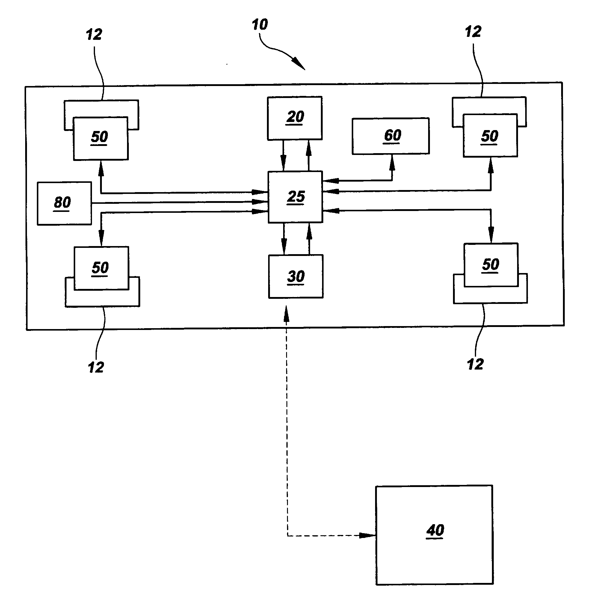
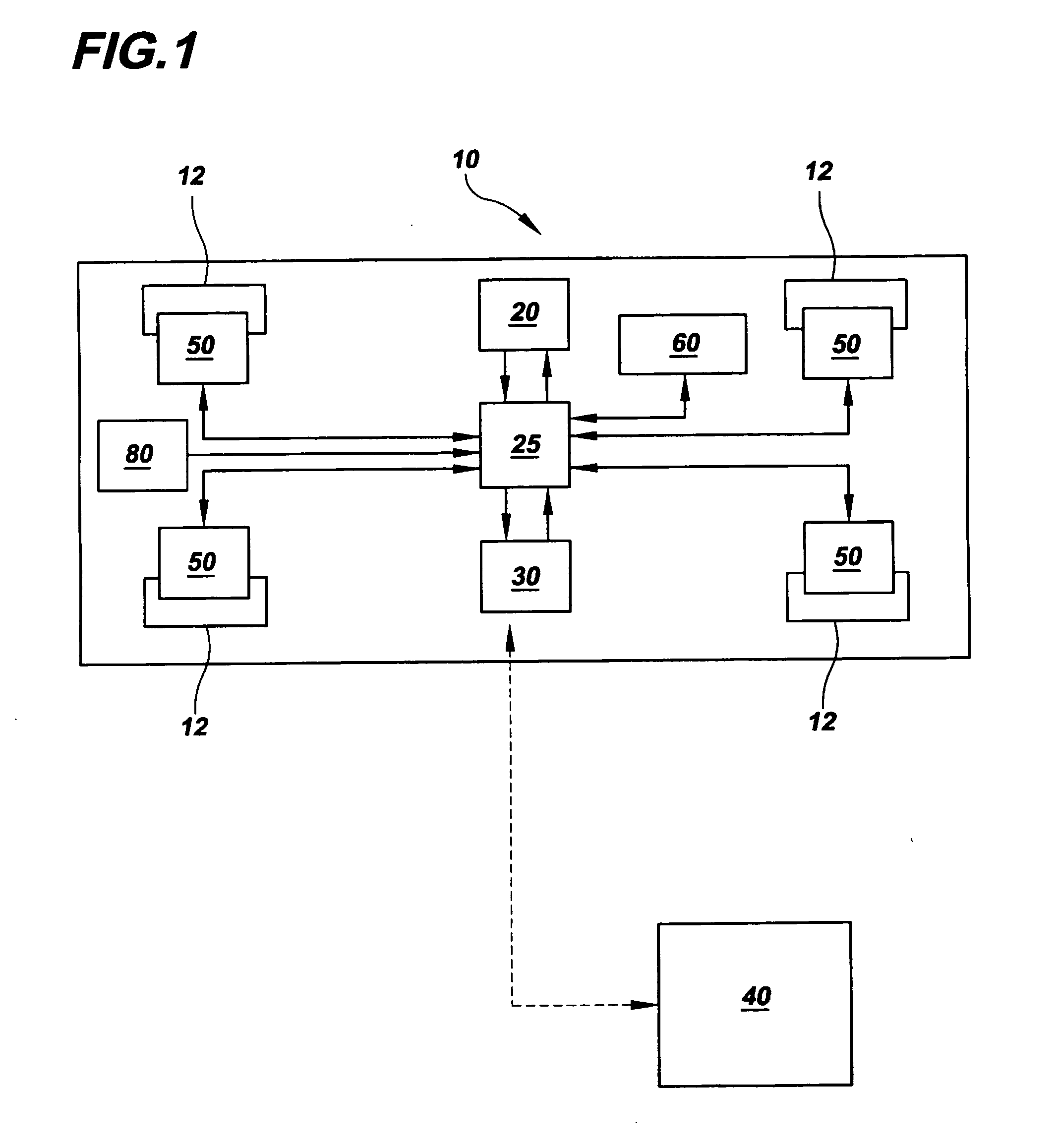
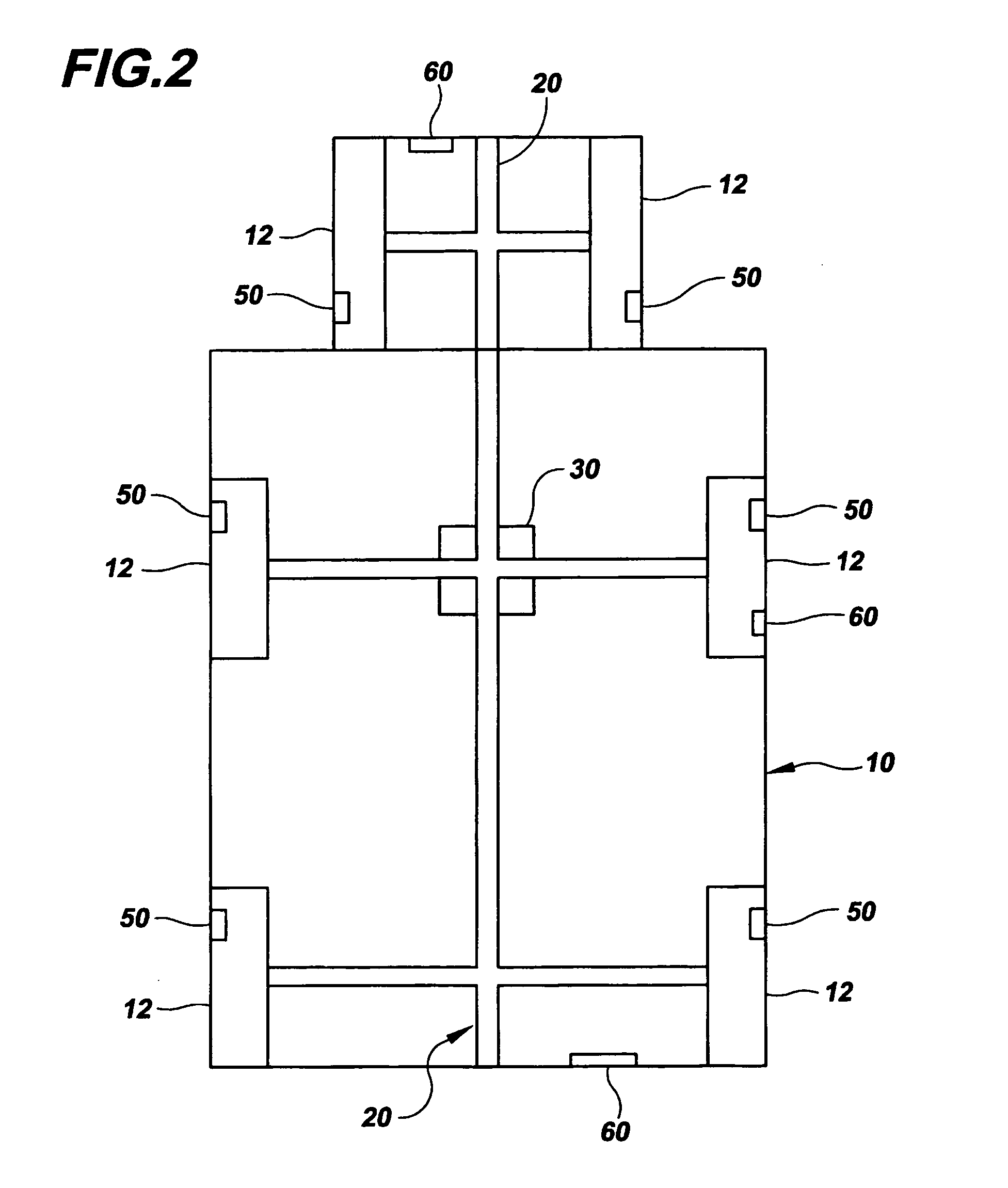
  • Tire management system and method
  • Tire management system and method

Examples


Embodiment Construction

[0026] Referring now to the figures of the drawing, the figures constitute a part of this specification and illustrate exemplary embodiments of the invention. It is to be understood that in some instances various aspects of the invention may be shown exaggerated or enlarged to facilitate an understanding of the invention.

[0027]FIG. 1 is a schematic illustration of a tire management system and its operation according to one aspect of the invention. A representative vehicle 10 having tires 12 is shown. One or more pressure gauges 50 positioned on the vehicle 10, for example, on tires 12 and / or a CTI system 20 or elsewhere on the vehicle 10, measure tire pressures. In one embodiment, the tire management system includes at least one pressure gauge 50 positioned on each tire 12 of the vehicle 10 such that each pressure gauge 50 is uniquely identified by the tire management system. For example, each pressure gauge may send a signal or frequency along with the pressure reading that allows...


PUM


Abstract

In one aspect, the invention is a system and method for improving vehicle operating conditions through the monitoring and adjustment of tire pressure in response to changing conditions. The system improves commercial vehicle productivity by reducing tire and fuel expenses, improving traction when needed, and reducing tire-induced shock-load damage to the vehicle axles and chassis. In another aspect, the invention is a tire management system, comprised of a tire inflation and deflation system positioned onboard said vehicle and operationally controlled by an onboard microprocessor-based control unit or by a remote centralized control-unit.

Description

CROSS REFERENCE TO RELATED APPLICATIONS [0001] The present application claims priority to U.S. Provisional Application No. 60 / 456,837, filed Mar. 21, 2003, which is incorporated herein by reference.FIELD OF THE INVENTION [0002] The present invention is directed to the field of the monitoring and maintenance of vehicle operating conditions and more particularly to a system and method for tire management. BACKGROUND OF THE INVENTION [0003] On-board vehicular tire pressure management systems that either inflate tires that have lost pressure or can both inflate and deflate vehicle tires to suit a range of operating conditions during vehicle operation, referred to as central tire inflation (CTI) systems, are known in the prior art. (See, for example, U.S. Pat. Nos. 5,141,589, 4,862,938, and U.S. Pat. No. 4,782,878 all to Mittal). Such CTI systems typically include a supply of pressurized air and controls for selectively changing existing tire pressure and for determining current tire pre...

Claims


Application Information

Patent Timeline
IPC IPC(8): B60CB60C23/00B60C23/04G06F17/00
CPCB60C23/003B60C23/0408B60C23/008B60C23/0483
Inventor INGRAM, RUPERT HENRY II
Owner INGRAM RUPERT HENRY II
Learn More