
Diagnostic imaging apparatus and method for limbs, particularly the hand by means of nuclear magnetic resonance

a nuclear magnetic resonance and diagnostic imaging technology, applied in the field of diagnostic imaging apparatus and method for limbs, can solve the problems of advanced damage and considerable damage caused by damage, and achieve the effects of improving positioning accuracy, simple construction, and efficient repositioning

Active Publication Date: 2005-04-28
ESAOTE
View PDF12 Cites 7 Cited by
  • Summary
  • Abstract
  • Description
  • Claims
  • Application Information

AI Technical Summary

Benefits of technology

The present invention provides a method for evaluating the progress of a pathology, particularly rheumatoid arthritis, in the end limbs or extremities of the body, particularly the hand or wrist, by using a nuclear magnetic resonance imaging apparatus. The method involves repositioning the same anatomical part in the same relative position with respect to the detection volume of the apparatus and detecting the changes in the position over time. The method can provide a reliable and accurate way of evaluating the progress of the pathology and allowing for proper intervention to correct it. The invention also includes a system for repositioning the patient's limb and a receiving coil for detecting the changes in position. The cast used for positioning the patient's limb can be made using a cylindrical or elliptical type and can be hinged or detachable from the bracket and receiving coil. The cast can be made of a material that is permeable to the excitation and receiving RF signals without generating noises or aberrations. The method and apparatus can help in evaluating the effectiveness of treatments and in making informed decisions on the proper course of treatment.

Problems solved by technology

However these damages are at an advanced phase of the pathology.
That can occur starting from young phases of the pathology before the damages caused by it can be of considerable level.

Method used


Image

  • Diagnostic imaging apparatus and method for limbs, particularly the hand by means of nuclear magnetic resonance
  • Diagnostic imaging apparatus and method for limbs, particularly the hand by means of nuclear magnetic resonance
  • Diagnostic imaging apparatus and method for limbs, particularly the hand by means of nuclear magnetic resonance

Examples


Embodiment Construction

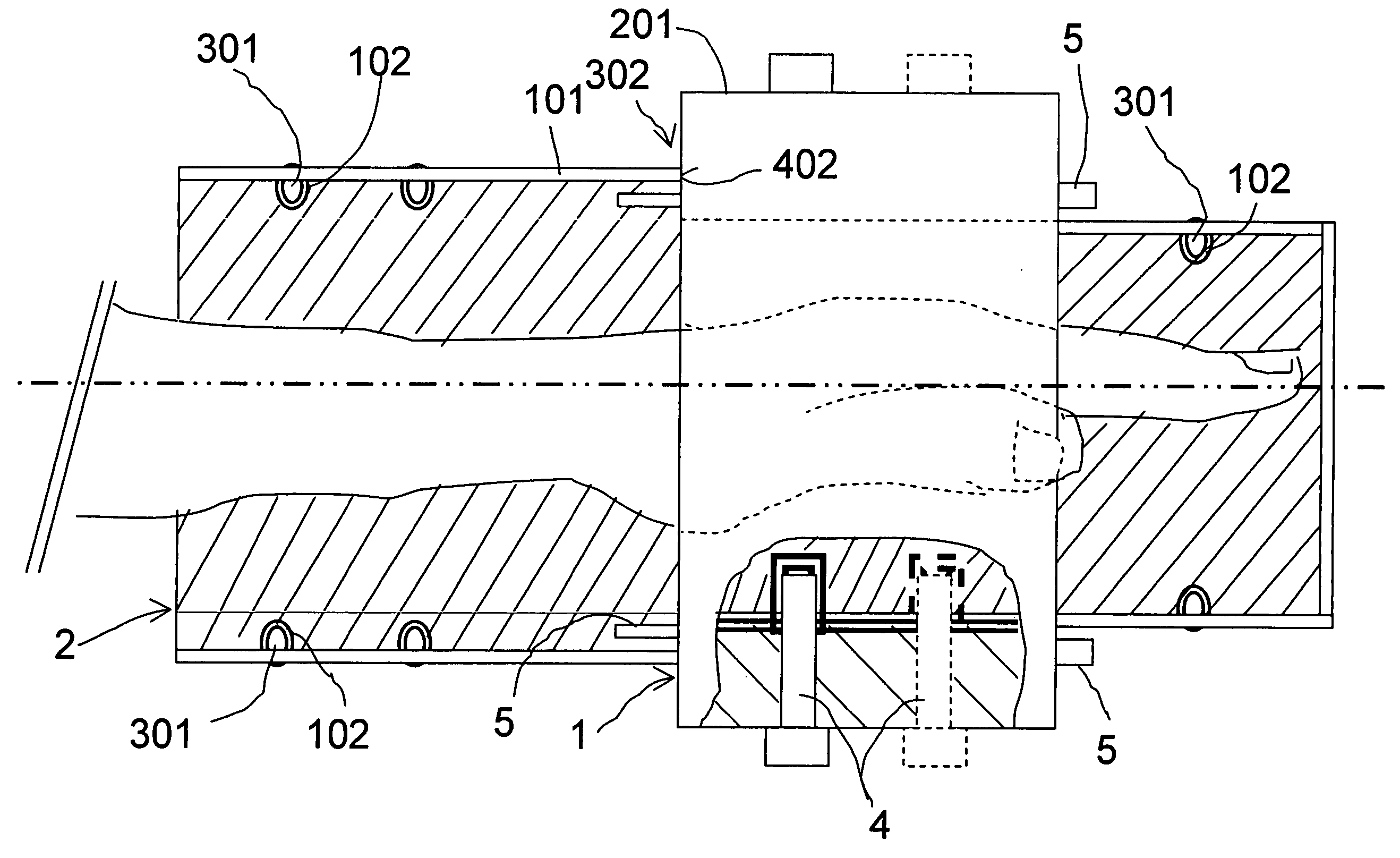
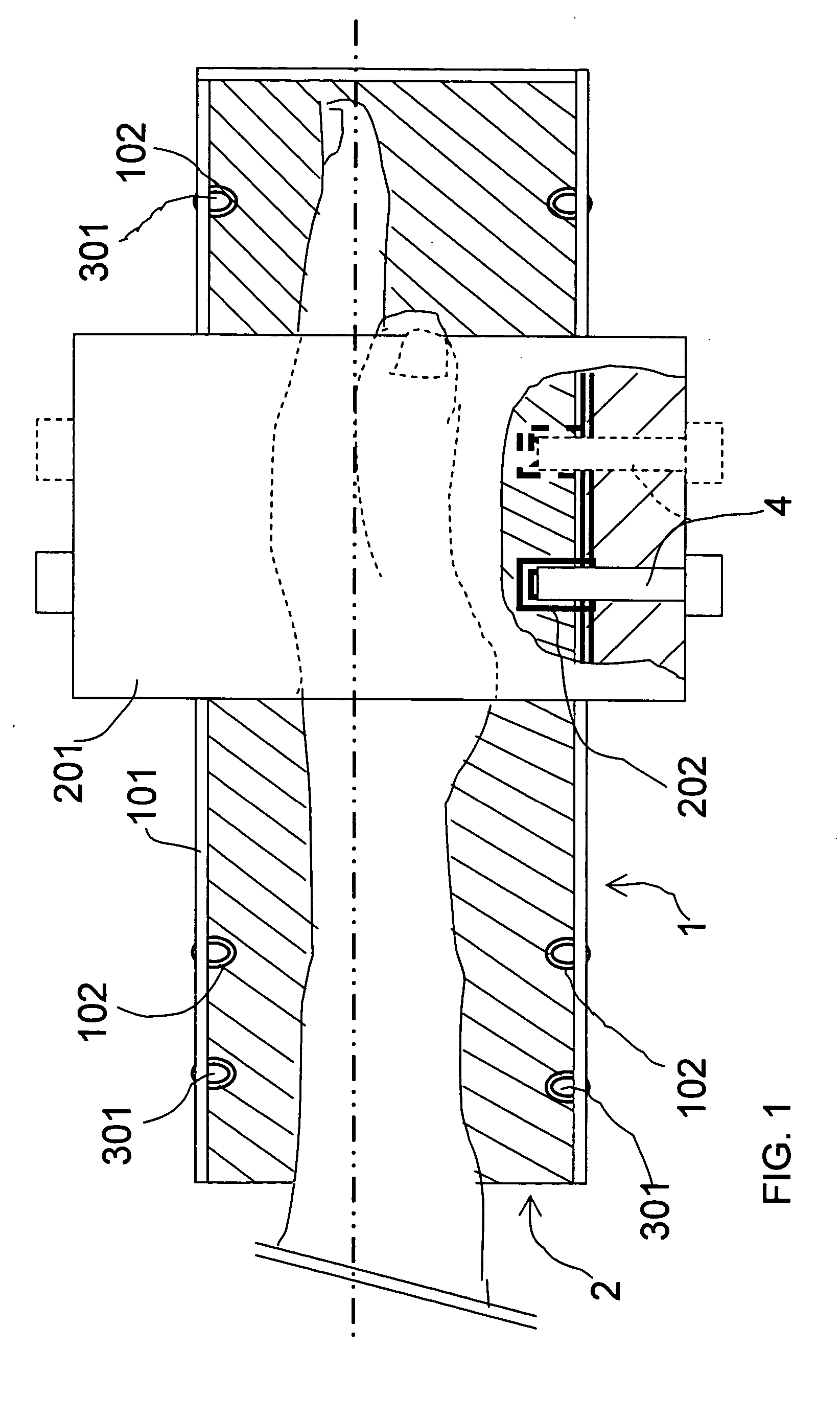
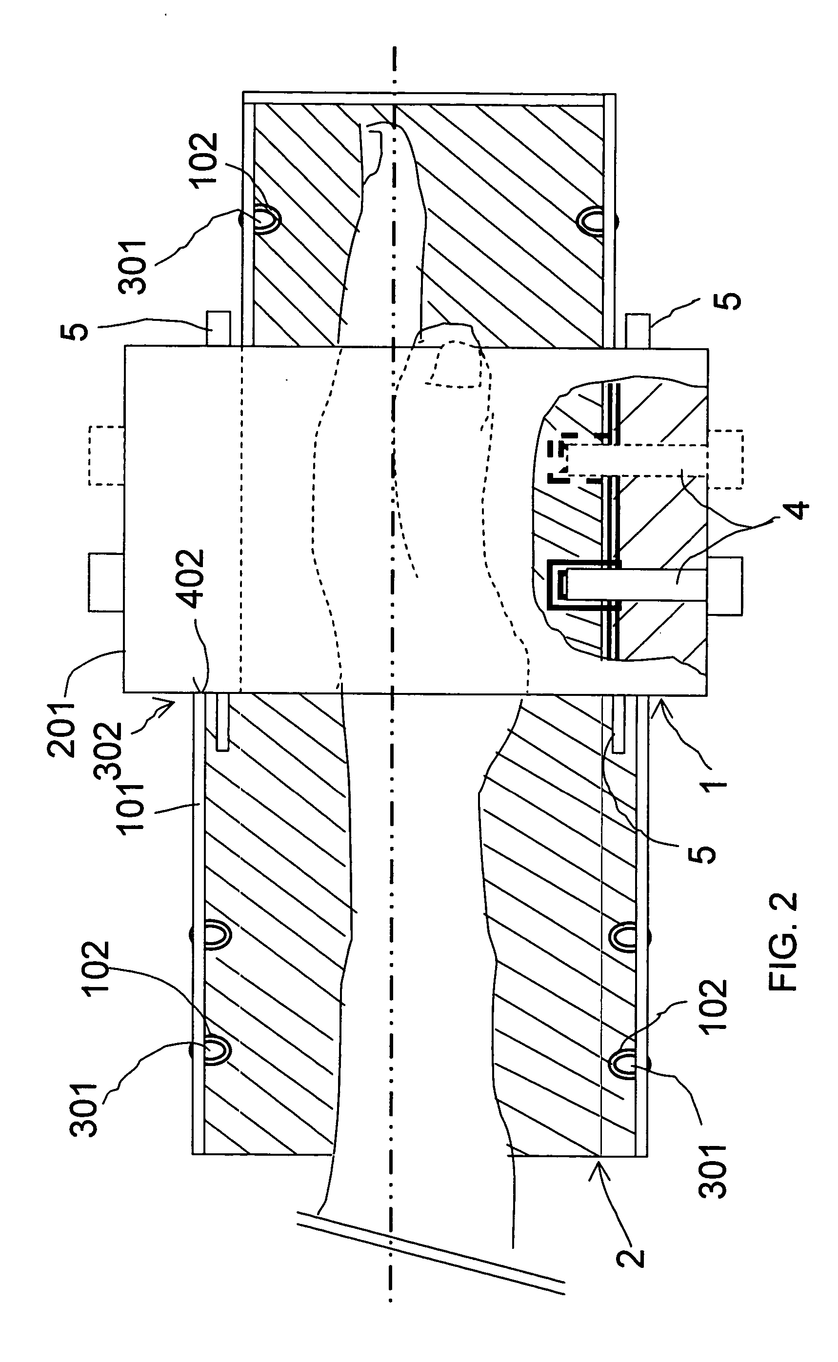
[0034] Referring to the figures, a device for properly positioning the hand according to a preferred embodiment of the present invention includes the combination of a hand supporting bracket and a receiving coil assembly generally indicated by 1 and the cast of the hand itself indicated by 2 and shown in axial section. A bracket 101 is composed of a lower part 101′ bearing the hand that can extend in the direction of the forearm to such extent up to the wrist and beyond it in the direction of the elbow. Said lower part 101′ is made with a concave surface with an arched section, particularly a circular one and extending for such angular width substantially of 180° C.

[0035] The bracket 101 extends inside an annular receiving coil 201 closed on itself and extending only for a partial axial length of the total length of the bracket 101.

[0036] The hand cast 2 is in the interior for the total length of the bearing lower part 101′ or for only a part thereof, preferably for the part subst...


PUM


Abstract

A method and apparatus for diagnostic imaging of a body part, by nuclear magnetic resonance, which method includes the steps of positioning the body part in a detection volume of a nuclear magnetic resonance imaging apparatus, inside a dedicated receiving coil; selecting the section or sections of said body part that has to be imaged and carrying out image detection by nuclear magnetic resonance; identifying and storing the detected images; and carrying out at intervals one or more subsequent image detections with nuclear magnetic resonance of the same body part and of the same section thereof as in the preceding image detections with nuclear magnetic resonance, positioning each time the body part in the same relative position with respect to the imaging volume of the nuclear magnetic resonance imaging apparatus.

Description

CROSS-REFERENCE TO RELATED APPLICATIONS [0001] The present application claims the priority of Italian Patent Application No. SV2003A000033, filed in Italy on Sep. 9, 2003, the entire content of which is incorporated herein by reference. BACKGROUND OF THE APPLICATION [0002] 1. Field of the Invention [0003] The present invention relates to a diagnostic imaging apparatus and method for limbs, particularly the hand, by means of nuclear magnetic resonance, which method comprises the steps of positioning the hand in a detection volume of a nuclear magnetic resonance imaging apparatus, inside a dedicated coil, of selecting the section or sections of the hand or wrist of which the image has to be detected and of carrying out the image detection by means of nuclear magnetic resonance. [0004] 2. Discussion of Related Art [0005] At present it has been found that in the evaluation of rheumatoid arthritis the images detected by nuclear magnetic resonance allow one to visualize pathological damag...

Claims


Application Information

Patent Timeline
Patent Type & Authority Applications(United States)
IPC IPC(8): A61B5/055A61B6/04
CPCA61B5/0555A61B6/0421A61B5/4528A61B5/055A61B5/702
Inventor CONTRADA, ORFEOSATRAGNO, LUIGI
Owner ESAOTE
Learn More