Structure connection of motion chair

a technology for connecting structures and motion chairs, which is applied in the direction of chairs, stools, domestic applications, etc., can solve the problems of increasing the difficulty level of conventional technology assembling the chairback, the structure of the fixed receiving frame b>140/b> is quite complicated, and the difficulty level of dismantling and assembling the chairback and the chair base can be greatly reduced, prolonging the use life of the structure connection, and reducing the fabrication cost

Inactive Publication Date: 2005-04-21
CHI CHING HUI
View PDF8 Cites 9 Cited by
  • Summary
  • Abstract
  • Description
  • Claims
  • Application Information

AI Technical Summary

Benefits of technology

[0006] It is a main object of the present invention to provide a structure connection of motion chair for using the engagement of the concaved portions of the supporting plates and supporting members to lower the difficulty level of assembling the chairback and the chair base; to provide a robust and brief structural design for prolonging the usage life of the structure connection and reduce the fabrication cost.
[0011] Hence, with the application of the present invention, the difficulty level of dismantling and assembling the chairback and the chair base can be greatly lowered; a robust and brief structural design can be provided for prolonging the usage life of the structure connection and reducing the fabrication cost.

Problems solved by technology

Moreover, the structure of the fixed receiving frames 140 is quite complicated and the fabrication cost thereof is high.
Since the chair having the functions of foot raising and inclining is quite heavy in weight and large in size, it is already not easy to lift the entire chairback upwards for a certain distance, and the additional work of aligning the fixed receiving frames 140 to the rear inclining bars 120 further increase the difficulty level of the conventional technology assembling the chairback 100 and the chair base 110.

Method used


Image

  • Structure connection of motion chair
  • Structure connection of motion chair
  • Structure connection of motion chair

Examples


Embodiment Construction

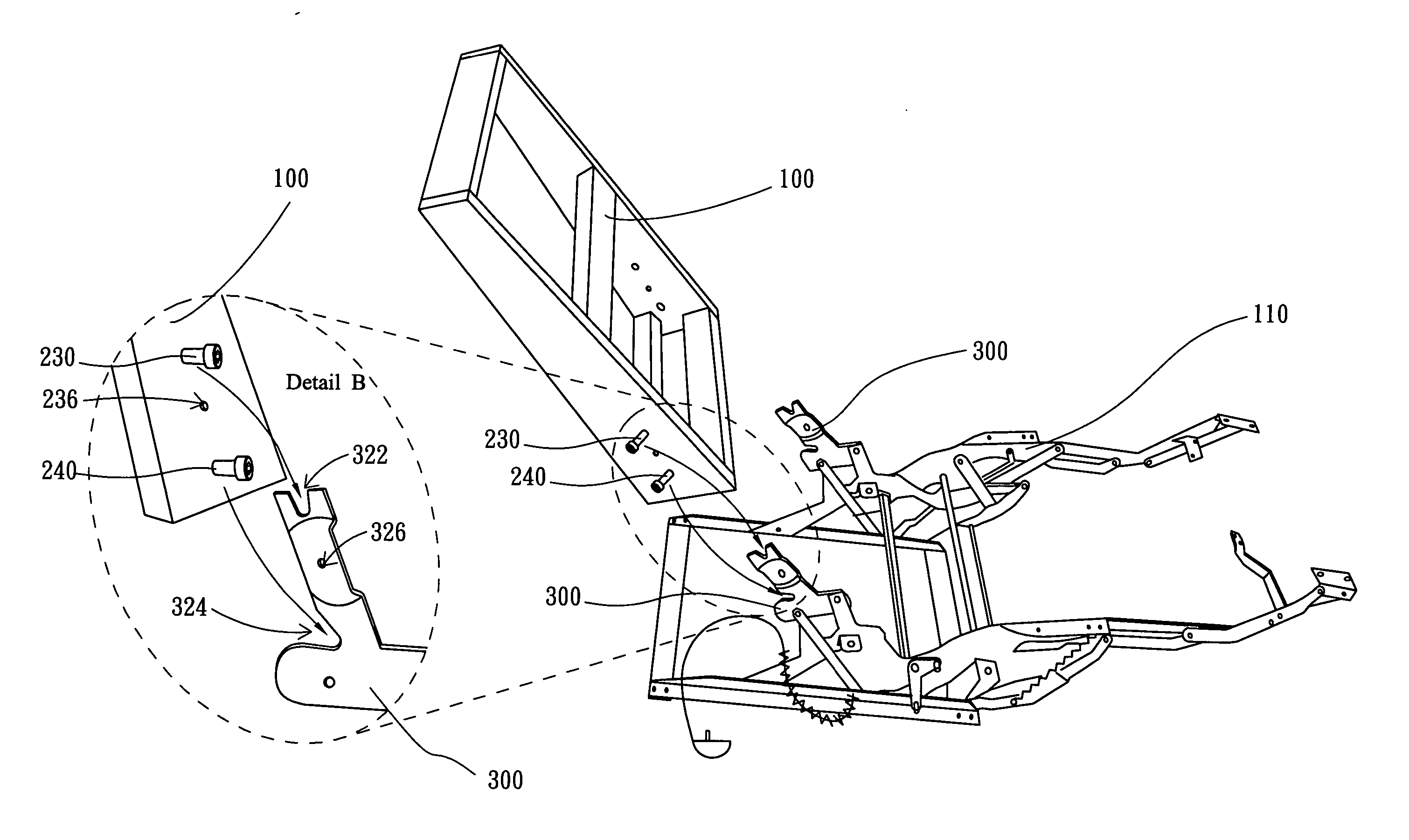
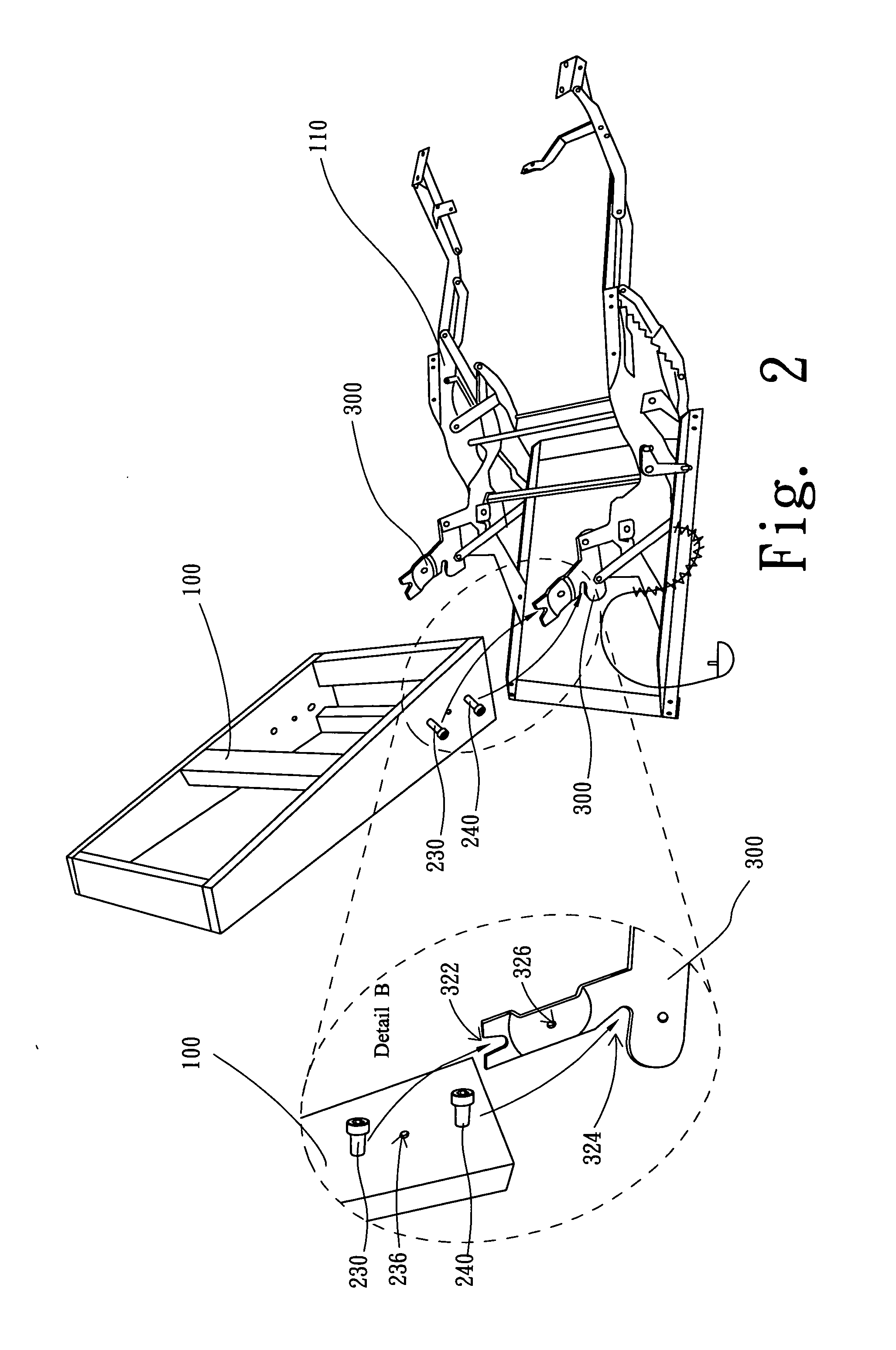
[0017] Referring to FIG. 2 and FIG. 3, FIG. 2 is an explosive view schematically showing a structure connection of motion chair of the present invention, and FIG. 3 illustrates a schematic assembly diagram of the structure connection of motion chair of the present invention. According to the present invention, a structure connection of motion chair is composed of a pair of supporting members 230, a pair of supporting members 240 and a pair of supporting plates 300, wherein the supporting members 230 are installed on both sides of a chairback 100, and the supporting members 240 are installed on both sides of the chairback 100, and the supporting plates 300 are installed on both sides of a chair base 110. The supporting members 230 respectively located on both sides of the chairback 100 are the same in material and shape; the supporting members 240 respectively located on both sides of the chairback 100 are the same in material and shape; and the supporting plates 300 respectively loc...


PUM


Abstract

A structure connection of motion chair is disclosed for connecting a chairback to a chair base. The structure connection of motion chair consists of a pair of first supporting members and a pair of second supporting members respectively installed on both sides of the chairback, and a pair of supporting plates respectively installed on both sides of the chair base. The second supporting members are respectively located below the first supporting members, and the supporting plates are respectively corresponding to the first supporting members and the second supporting members, wherein the supporting plates are used for engaging with the first and second supporting members respectively, whereby the chairback and the chair base are connected together.

Description

FIELD OF THE INVENTION [0001] The present invention relates to a structure connection of motion chair, and more particularly, to a chairback connection structure that can be easily dismantled and assembled. BACKGROUND OF THE INVENTION [0002] Generally, for the sake of delivery convenience, a product is commonly expected with the best possibility to be dismantled into several parts beforehand, those parts are assembled after arriving the destination, thereby reducing the space occupied by the product while being conveyed, thus saving the delivery cost. For a chair product, particularly for the chair with the functions of foot raising and inclining, such as a massage chair, a lounger or a sofa, etc., separating the chairback from the chair base is the major method for greatly reducing the product space in convey. On the other hand, since the DIY (Do It Yourself) market has been more and more popular with consumers, the function of rapidly and briefly dismantling and assembling a produ...

Claims


Application Information

Patent Timeline
IPC IPC(8): A47C7/42
CPCA47C7/42
Inventor CHI, CHING-HUI
Owner CHI CHING HUI
Why Eureka
Try Eureka