
Integrated anchoring system and composite plate for a trailer side wall joint

a technology of integrated anchoring system and composite plate, which is applied in the directions of transportation and packaging, load securing, transportation items, etc., can solve the problem that the track member can be easily damaged, and achieve the effect of less damag

Inactive Publication Date: 2005-04-07
WABASH NATIONAL
View PDF2 Cites 9 Cited by
  • Summary
  • Abstract
  • Description
  • Claims
  • Application Information

AI Technical Summary

Benefits of technology

The invention is a joint between the side walls of a trailer body that includes an anchoring system. The anchoring system includes track members that are attached to the side walls and beams that support cargo or a removable deck. The track members can be removed from the side walls without dismantling the entire joint. The invention also includes splicing members that are attached to the side walls on the outside of the trailer body. The invention has several technical effects, including being less damageable by forklifts, reinforcing the track member, and allowing for easy removal of the anchoring system. The invention is made of roll formed 14 gauge steel, which improves manufacturing.

Problems solved by technology

As a result, the track members can be easily damaged by forklifts or other means.

Method used


Image

  • Integrated anchoring system and composite plate for a trailer side wall joint
  • Integrated anchoring system and composite plate for a trailer side wall joint
  • Integrated anchoring system and composite plate for a trailer side wall joint

Examples


first embodiment

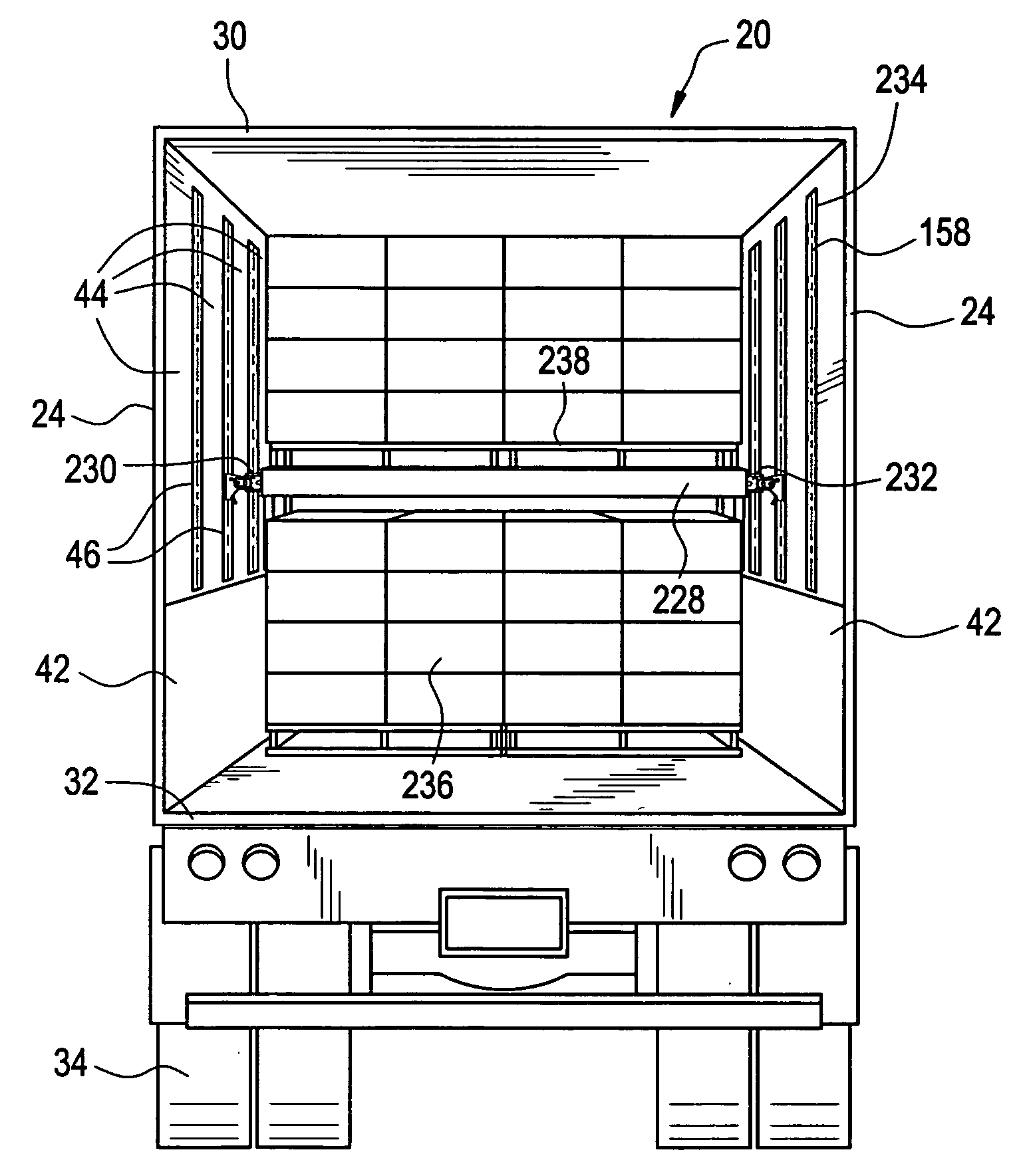
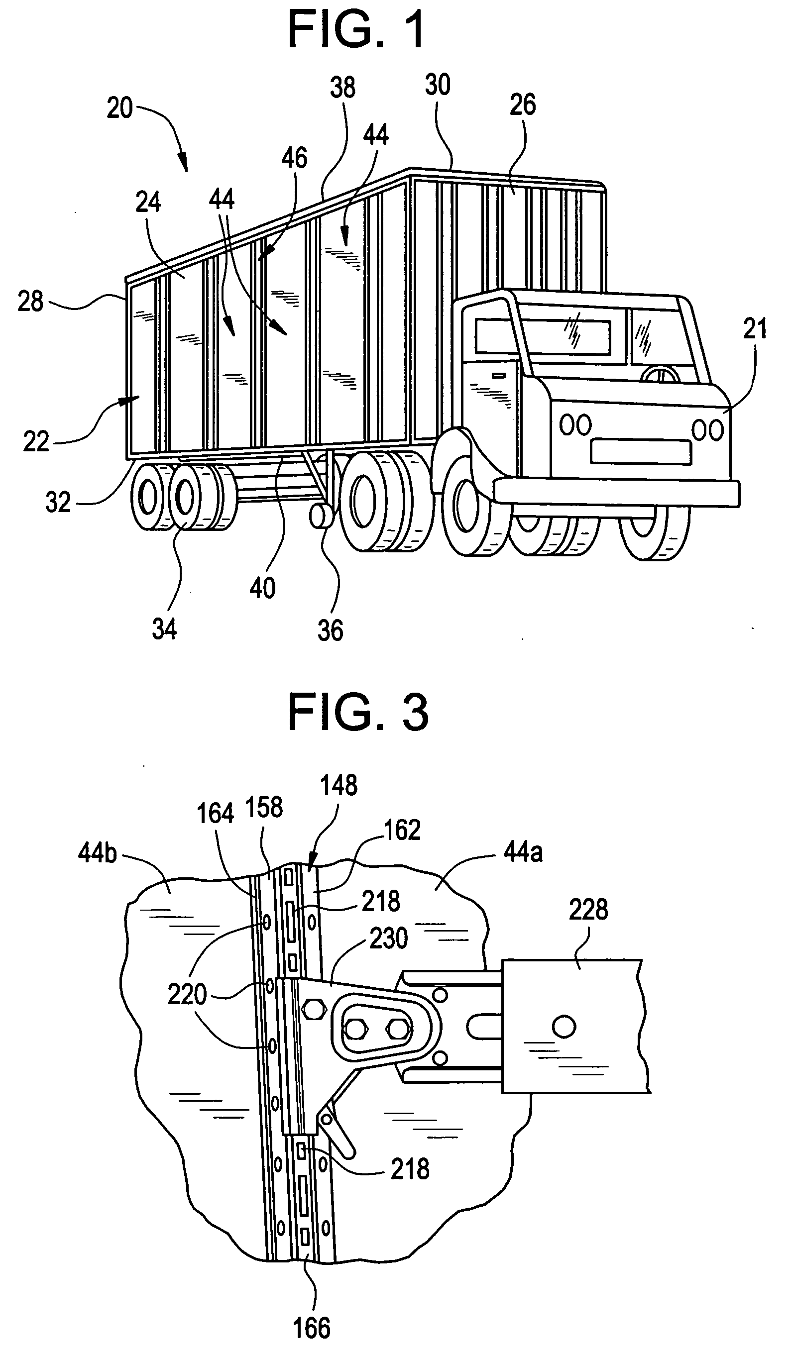
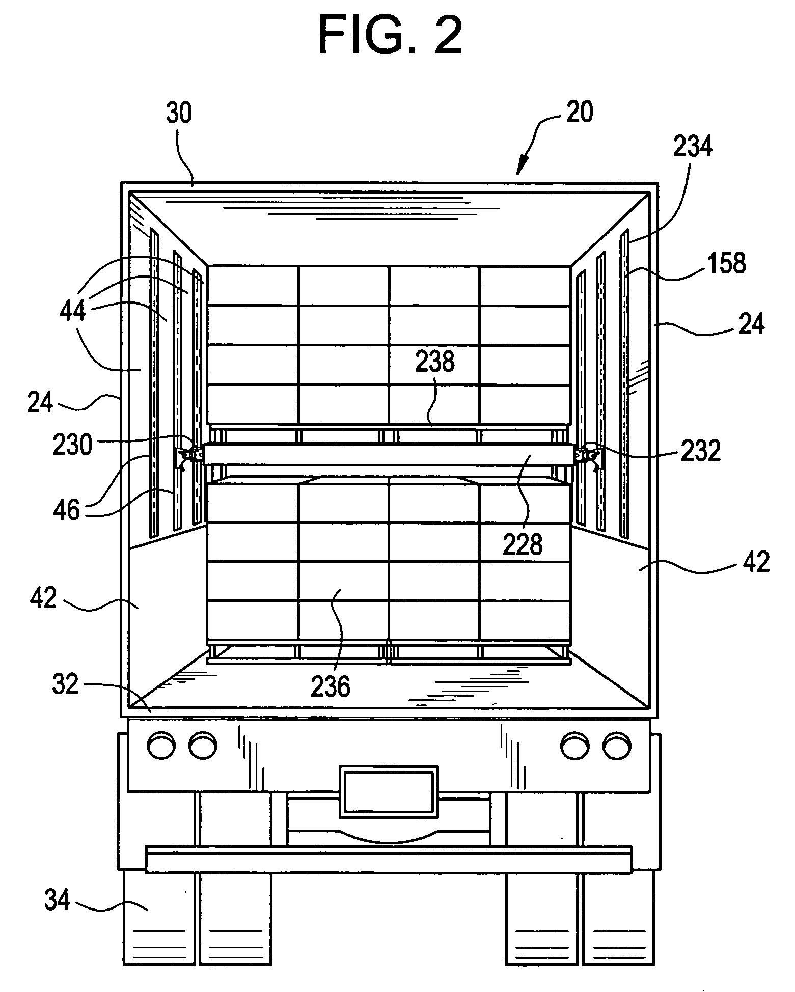
[0035] Attention is now invited to the novel joint 46 which includes the anchoring system 148 shown in FIGS. 2-7. First and second composite plates 44a, 44b are shown and are joined together by a track member 158 on the inside of the trailer 20 which extends from a point above the scuff plate 42 to a point proximate to, but spaced from, the roof 30 of the trailer 20, as shown in FIG. 2, and by the splicing plate 50 on the outside of the trailer 20 which extends along the entire height of the plates 44a, 44b. The ends 60a, 60b of the plates 44a, 44b are spaced apart from each other when joined by the track member 158 and the splicing plate 50 such that a portion of the track member 158 is positioned between the ends 60a, 60b of the plates 44a, 44b, as will be discussed in more detail herein.

[0036] The track member 158 is an elongated member having a first end portion 162, a second end portion 164 and a middle portion 166 therebetween that is integral with the first end portion 162 an...

second embodiment

[0066] Attention is now invited to the novel joint 46 which includes the anchoring system 348 shown in FIGS. 8-13. First and second composite plates 44a, 44b are shown and are joined together by a track member 358 on the inside of the trailer 20 which extends from a point above the scuff plate 42 to a point proximate to, but spaced from, the roof 30 of the trailer 20 and by a splicing plate 50 on the outside of the trailer 20 which extends along the entire height of the plates 44a, 44b. The ends 60a, 60b of the plates 44a, 44b are spaced apart from each other when joined by the track member 358 and the splicing plate 50 such that a portion of the track member 358 is positioned between the ends 60a, 60b of the plates 44a, 44b, as will be discussed in more detail herein.

[0067] The track member 358 is an elongated member having a first end portion 362, a second end portion 364 and a middle portion 366 therebetween that is integral with both the first end portion 362 and the second end ...


PUM


Abstract

The present invention provides a novel joint which includes an anchoring system between composite plate side walls of a trailer body. The anchoring system includes track members which are provided at multiple points on each side wall. Beams extend between the respective track members by attachments and are attached thereto. The beams can be moved up and down along the tracks and support cargo or a removable deck which supports the cargo. The track members can also be removed from the joints without dismantling the entire joint. Splicing members are attached at the joints on the outside of the trailer body.

Description

CROSS-REFERENCE [0001] This application is a Continuation of copending U.S. application Ser. No. 10 / 192,913, filed on Jul. 10, 2002, and entitled “Integrated Anchoring System and Composite Plate for a Trailer Side Wall Joint”, which, in turn, claims the domestic priority of U.S. Provisional Application Ser. No. 60 / 304,432, filed on Jul. 10, 2001, and entitled “Integrated Anchoring System and composite Plate for a Trailer Side Wall Joint”.BACKGROUND OF THE INVENTION [0002] Many different kinds of anchoring systems exist for use in the interior of trailers for supporting cargo or a removable deck which supports cargo. Two such systems are provided by Kinedyne Corporation and Ancra International LLC. [0003] Each of these anchoring systems have a number of elongated track members which generally run along the interior side walls of a trailer, from a position proximate to the roof of the trailer to a position proximate to a top of a scuff plate provided on the respective side wall proxim...

Claims


Application Information

Patent Timeline
Patent Type & Authority Applications(United States)
IPC IPC(8): B60P7/15B62D33/04
CPCB62D33/046B60P7/15
Inventor EHRLICH, RODNEY P.
Owner WABASH NATIONAL
Learn More