Ladder stand-off

a technology of ladders and stand-offs, which is applied in the direction of scaffolds, machine supports, and machine accessories, can solve the problems of large and bulky stand-offs, easy loss or breakage of moving parts, and many known stand-offs that are not readily used with both flat and corner surfaces

Inactive Publication Date: 2005-04-07
UNDERHILL PHILIP ORLANDO +2
View PDF11 Cites 2 Cited by
  • Summary
  • Abstract
  • Description
  • Claims
  • Application Information

AI Technical Summary

Benefits of technology

[0006] The above-mentioned need is met by the present invention, which provides a ladder stand-off having an extension beam and first and second stand-off sections slidingly mounted on the extension beam, so as to provide an adjustable span. The first stand-off section includes a first support beam and a first arm fixedly connected to the first support beam, and the second stand-off section includes a second support beam and a second arm fixedly connected to the second support beam. A contact element is pivotally contacted to the outer end of each arm. In one embodiment, each arm is connected to the respective support beam at a point located between the two ends of the support beam, and the two arms extend in an outward direction so as to be angularly divergent with respect to each other. The ladder stand-off also includes means for being detachably secured to a ladder.

Problems solved by technology

However, many known stand-offs are not readily used with both flat and corner surfaces or require manual adjustment of various moving parts to permit use with different surfaces.
Such moving parts are susceptible to becoming lost or broken.
Many current stand-offs are also big and bulky and thus not suitable for use in tight spaces.

Method used


Image

  • Ladder stand-off
  • Ladder stand-off
  • Ladder stand-off

Examples


Embodiment Construction

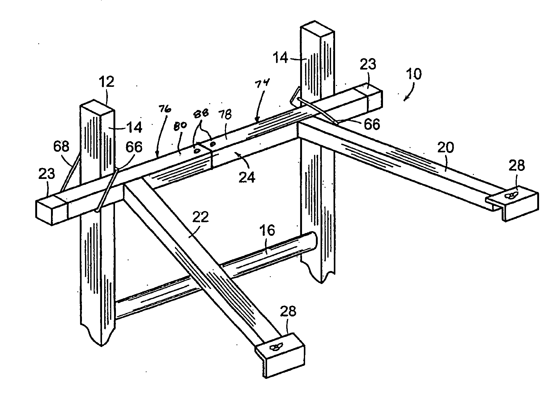
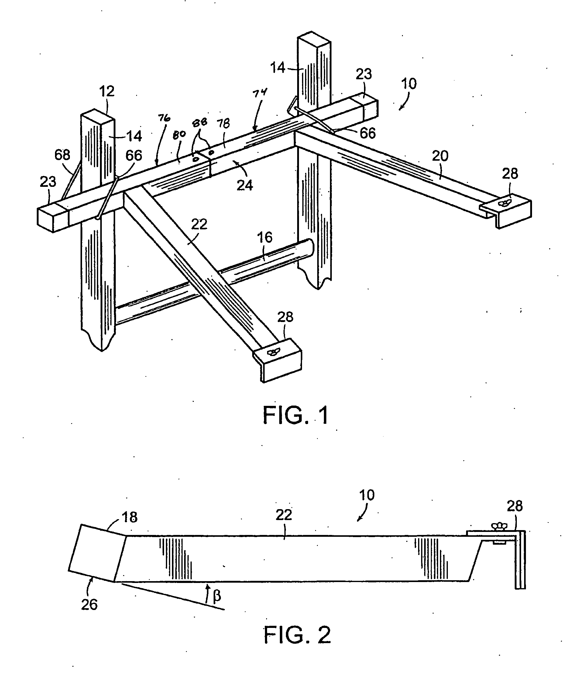
[0026] Referring to the drawings wherein identical reference numerals denote the same elements throughout the various views, FIG. 1 shows a ladder stand-off 10 detachably secured to a conventional ladder 12. The ladder 12 illustrated in the Figures is a common lean-on ladder having a pair of laterally spaced side rails 14 interconnected by a plurality of longitudinally spaced rungs 16. The ladder stand-off 10 can be used with extendible and non-extendible ladders. It is also possible to use the ladder stand-off 10 with folding step ladders when folded closed and used in the manner of a lean-on ladder (i.e., leaned against a wall or other vertical surface).

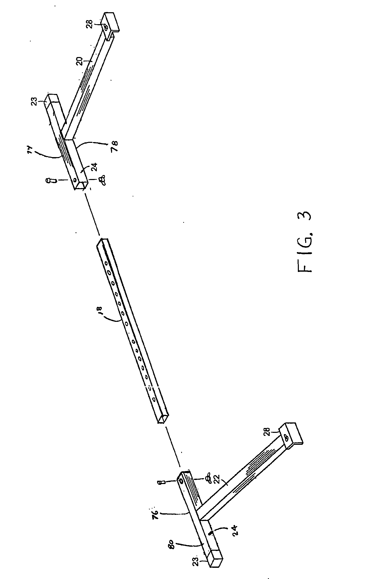
[0027] Referring to FIGS. 1-8, the ladder stand-off 10 includes an extension beam 18 and first and second stand-off sections 74 and 76 slidingly mounted on the extension beam 18. The extension beam 18 should be suitably strong and rigid and is preferably a straight piece having a predetermined length. In one embodiment, the extens...


PUM


Abstract

A ladder stand-off includes an extension beam and first and second stand-off sections slidingly mounted on the extension beam, so as to provide an adjustable span. Each stand-off section includes a support beam and an arm fixedly connected to the first support beam. A contact element is pivotally contacted to the outer end of each arm, allowing the device to be used with flat, curved and corner surfaces. The two arms preferably extend in an outward direction so as to be angularly divergent with respect to each other. The device can also be implemented as a ladder stand-off kit having multiple extension beams of different lengths that can be used interchangeably with the two ladder stand-off sections. In this case, the desired extension beam would be assembled with the first and second stand-off sections to form a ladder stand-off.

Description

CROSS REFERENCES TO RELATED APPLICATIONS [0001] This application is a Continuation-In-Part of copending U.S. patent application Ser. No. 10 / 680,648, entitled “LADDER STAND-OFF” and filed Oct. 7, 2003.BACKGROUND OF THE INVENTION [0002] This invention relates generally to ladder stand-offs and more particularly to ladder stand-offs useful in corner applications. [0003] Ladders are commonly used for many tasks to enable the user to reach locations that otherwise could not be reached. One of the most common types of ladders is the lean-on ladder which comprises a pair of laterally spaced side rails interconnected by a plurality of longitudinally spaced rungs. In use, the bottom of the ladder is supported on the ground or a floor and the top of the ladder is placed against a wall or similar vertical surface. Generally, lean-on ladders should be oriented at an angle of lean (i.e., the angle between the ladder and the ground or floor) of approximately 70-80 degrees for safe and stable depl...

Claims


Application Information

Patent Timeline
Patent Type & Authority Applications(United States)
IPC IPC(8): E06C7/48
CPCE06C7/482E06C7/48
Inventor UNDERHILL, PHILIP ORLANDOHEAFEY, PAMELA A.HEAFEY, MICHAEL S.
Owner UNDERHILL PHILIP ORLANDO
Why Eureka
Try Eureka