
Data recording method for optical disk drive

Inactive Publication Date: 2005-03-31
MEDIATEK INC
View PDF10 Cites 3 Cited by
  • Summary
  • Abstract
  • Description
  • Claims
  • Application Information

AI Technical Summary

Benefits of technology

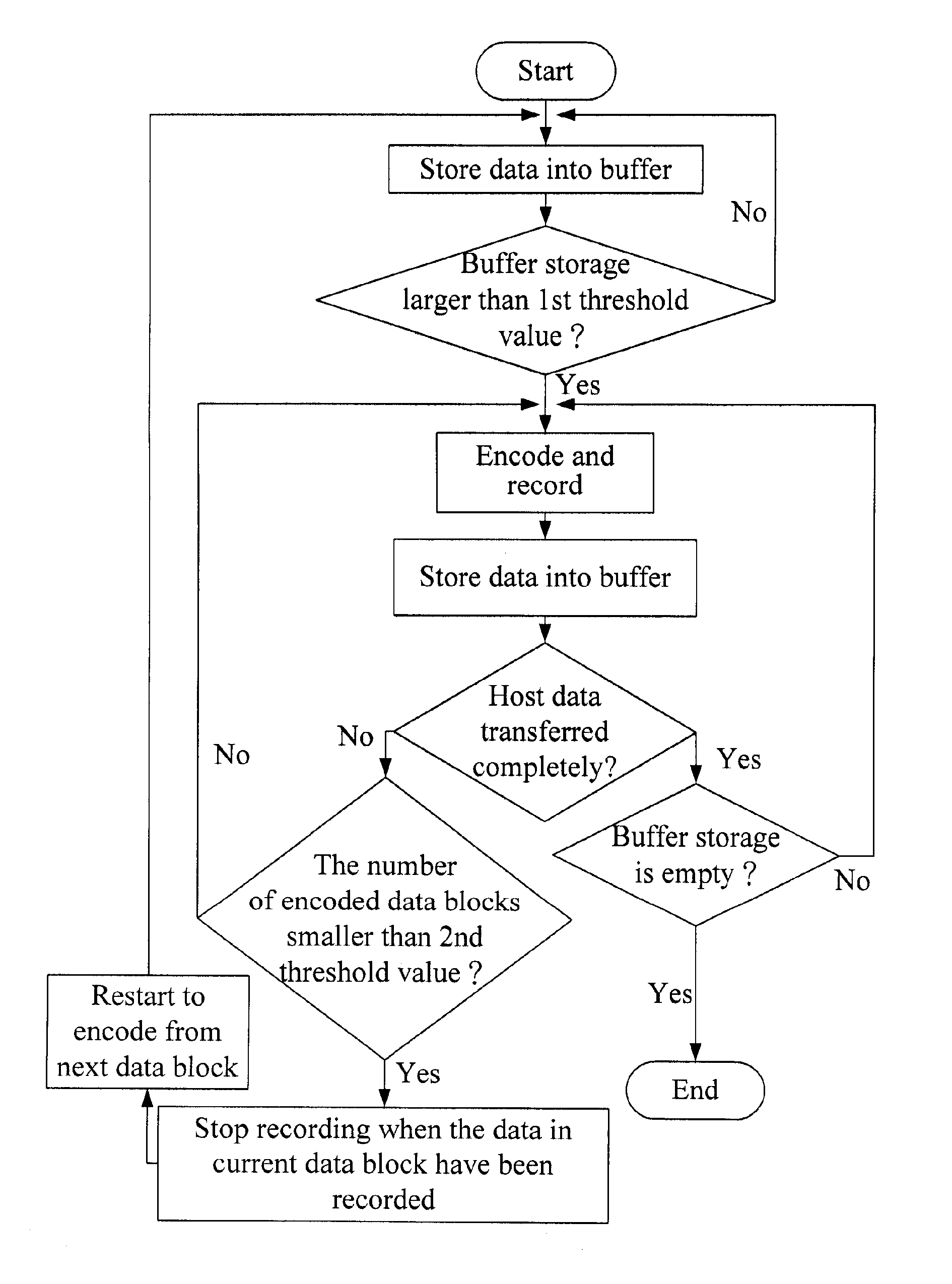
[0007] The objective of the present invention is to provide a data recording method for an optical disk drive for dealing with the event of recording interruption, by which recording manners can be unitized and the inferior recording quality caused by servo signal errors can be avoided.

Problems solved by technology

Furthermore, the inaccuracy of the start recording position may result in data loss.

Method used


Image

  • Data recording method for optical disk drive
  • Data recording method for optical disk drive
  • Data recording method for optical disk drive

Examples


first embodiment

[0016]FIG. 3 is the illustrative diagram of the data recording method for an optical disk drive of the first embodiment in accordance with the present invention, which shows the situation when a buffer under run occurs. The buffer under run is a situation that the number of data blocks including data and ECCs in the buffer, which is available to be recorded, is smaller than a threshold value. Generally, a data block includes a main data area for storing the host data and an auxiliary data area for storing the ECCs. When a buffer under run is detected, the data recording doesn't be interrupted right away. In this embodiment, when the buffer under run occurs, the data of the data block (N) are being recorded. Before the data blocks stored in the buffer are used up, the recording doesn't stop until at least the main data of the data block (N) stored in the buffer have been recorded, i.e., the interruption occurs in the auxiliary data area of the data block (N). In general, the buffer i...

second embodiment

[0020]FIG. 5 is the illustrative diagram for the data recording method for an optical disk drive of the second embodiment, which shows the situation when a servo signal error occurs, and is applied to a rewritable disk. The servo error is an error on the servo system of an optical disk drive that results in the incorrectness of record, such as the motor control error on the servo system caused by vibration, disk track locking error or laser defocusing error. If the servo error occurs in the data block (N−1), and the time to detect the servo error is at the end of the data block (N−1), the recording cannot be timely interrupted in the data block (N−1) because the time to detect the servo signal is too close to the data block (N). Therefore, the recording is actually interrupted in the data block (N). Because the buffer under run only relates to the problem that data cannot be transferred timely, the data recording quality before the interruption, in general, is not affected. However,...


PUM


Abstract

A data recording method for an optical disk drive is implemented by the following steps. First, one or more data blocks are encoded and recorded sequentially, and it detects if a buffer under run occurs. If a buffer under run occurs, the recording does not stop immediately until at least the main data of the data block being currently recorded have been recorded completely. Afterwards, it restarts to encode and record from the data block next to the data block where the recording stops. Moreover, the recording also can stops if a servo error is detected, and the data restart to encode and record from the data block where the recording stops or at least one data block preceding the data block where the recording stops.

Description

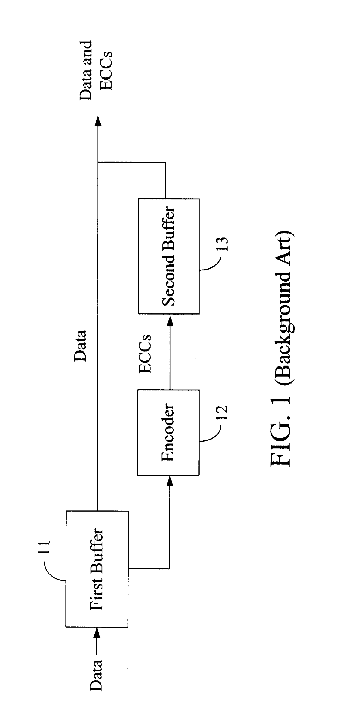
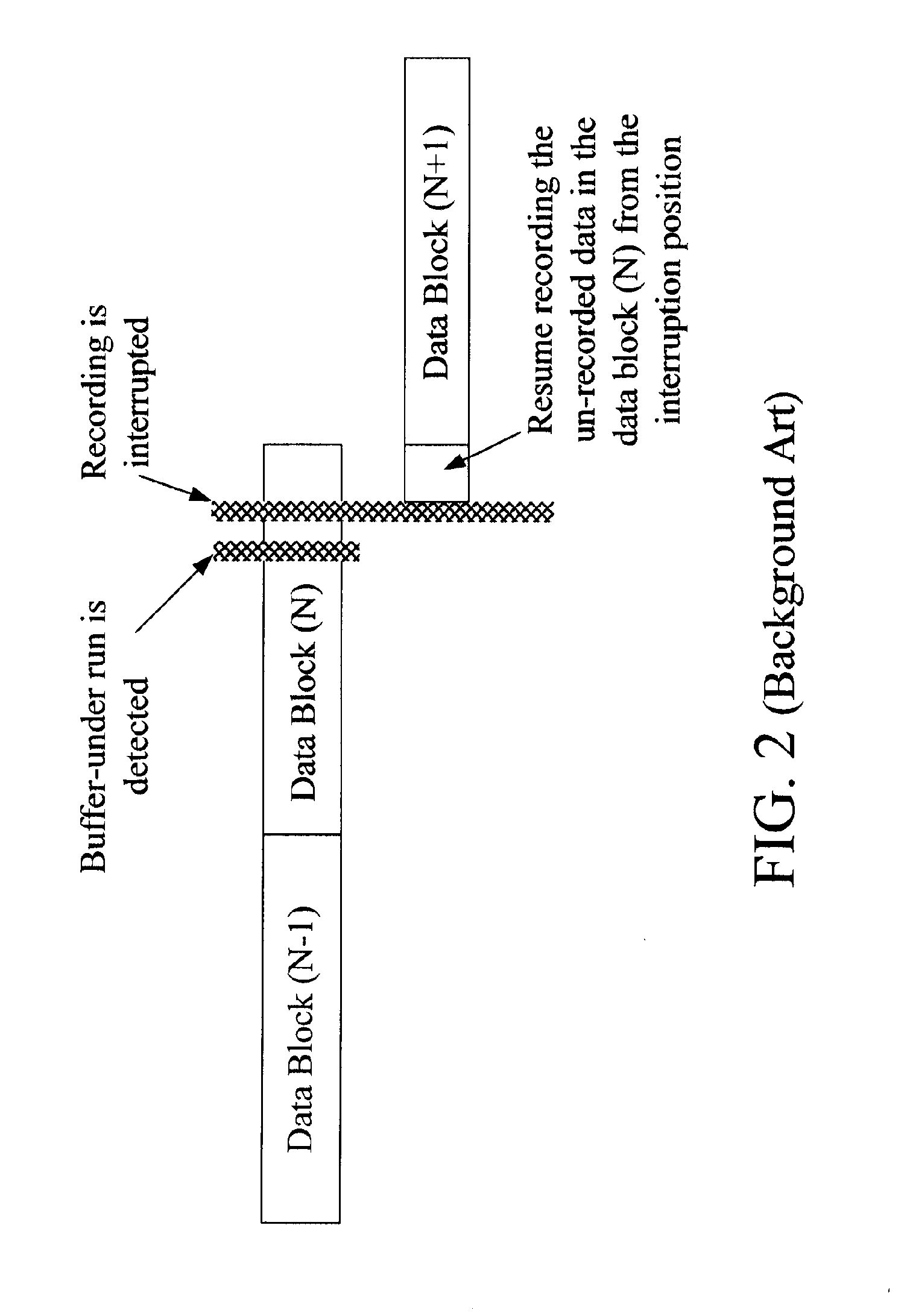
BACKGROUND OF THE INVENTION [0001] (A) Field of the Invention [0002] The present invention is related to a data recording method for an optical disk drive, more specially, to a data recording method for an optical disk drive for dealing with the event of recording interruption. [0003] (B) Description of the Related Art [0004] If abnormal servo signals of an optical disk drive caused by, for example, vibration, track-locking errors on a disk or laser defocusing, are detected, or a so-called buffer under run occurs because the host transfer speed cannot catch up with the recording speed, the recording is interrupted. The recording is not continued until the vibration stops, the track is locked again, the laser refocuses or sufficient data is supplemented in the buffer. [0005] In general, the data to-be-recorded are divided into data blocks in advance, and are sequentially recorded in unit of data blocks. As shown in FIG. 1, the host data to be recorded are transferred to a first buffe...

Claims


Application Information

Patent Timeline
IPC IPC(8): G11B20/10G11B27/36G11C29/00H03M13/00
CPCG11B20/10527G11B27/36G11B2020/1062G11B2220/2562G11B2020/10972G11B2220/2537G11B2020/10814
Inventor WENG, YIH-SHINCHEN, HONG-CHING
Owner MEDIATEK INC
Learn More