
Machine and method for the continuous treatment of a fabric

a fabric and machine technology, applied in the direction of spin dryers, drying machines with progressive movements, lighting and heating apparatus, etc., can solve the problems of frequent stoppage of the machine for loading and unloading, loss of production time and labor costs, and significant energy expenditur

Inactive Publication Date: 2005-03-31
CORAMTEX
View PDF16 Cites 6 Cited by
  • Summary
  • Abstract
  • Description
  • Claims
  • Application Information

AI Technical Summary

Benefits of technology

[0014] The pivoting movement of the transfer member, which may in practice be a double Venturi tube, facilitates extraction of the fabric from the pick-up tank and its expulsion on the opposite side. The suction of air performed on the opposite side of each grille to the side from where the fabric is “fired out” by the transfer member, increases the air flow which conveys the fabric and causes it to strike the grille. This increases the treatment efficiency of the machine. A greater treatment efficiency also allows a reduction in the number of passes which each section of fabric must undergo inside the machine, with a consequent increase in the productivity of the machine itself. As a result of the sucked-in air flow, it is possible to achieve a high acceleration of the fabric upon every reversal in the direction of feeding and therefore achieve the necessary speed for obtaining effective treatment even when the supply of fabric present inside the machine is relatively small.
[0019] The treatment of fabric in rope form produces results which are better in terms of effectiveness of the treatment, since greater mechanical processing of the fibers is achieved, with a consequent breakage of the said fibers and softening of the fabric.

Problems solved by technology

This type of machine has the drawback that the machine must be frequently stopped for loading and unloading.
This results in lost production time and high labor costs.
The need to depressurize and cool the machine (when it is working under pressure and / or at temperature) also results in a notable expenditure of energy.
The mechanical processing operations which may be performed on the fabric with this machine are somewhat limited in effect.
Moreover, conveying of the fabric is difficult owing to the winding nature of the path and the limited efficiency of the air jets which act on the fabric during treatment.
In this case also, the efficiency of the treatment is limited.

Method used


Image

  • Machine and method for the continuous treatment of a fabric
  • Machine and method for the continuous treatment of a fabric
  • Machine and method for the continuous treatment of a fabric

Examples


Embodiment Construction

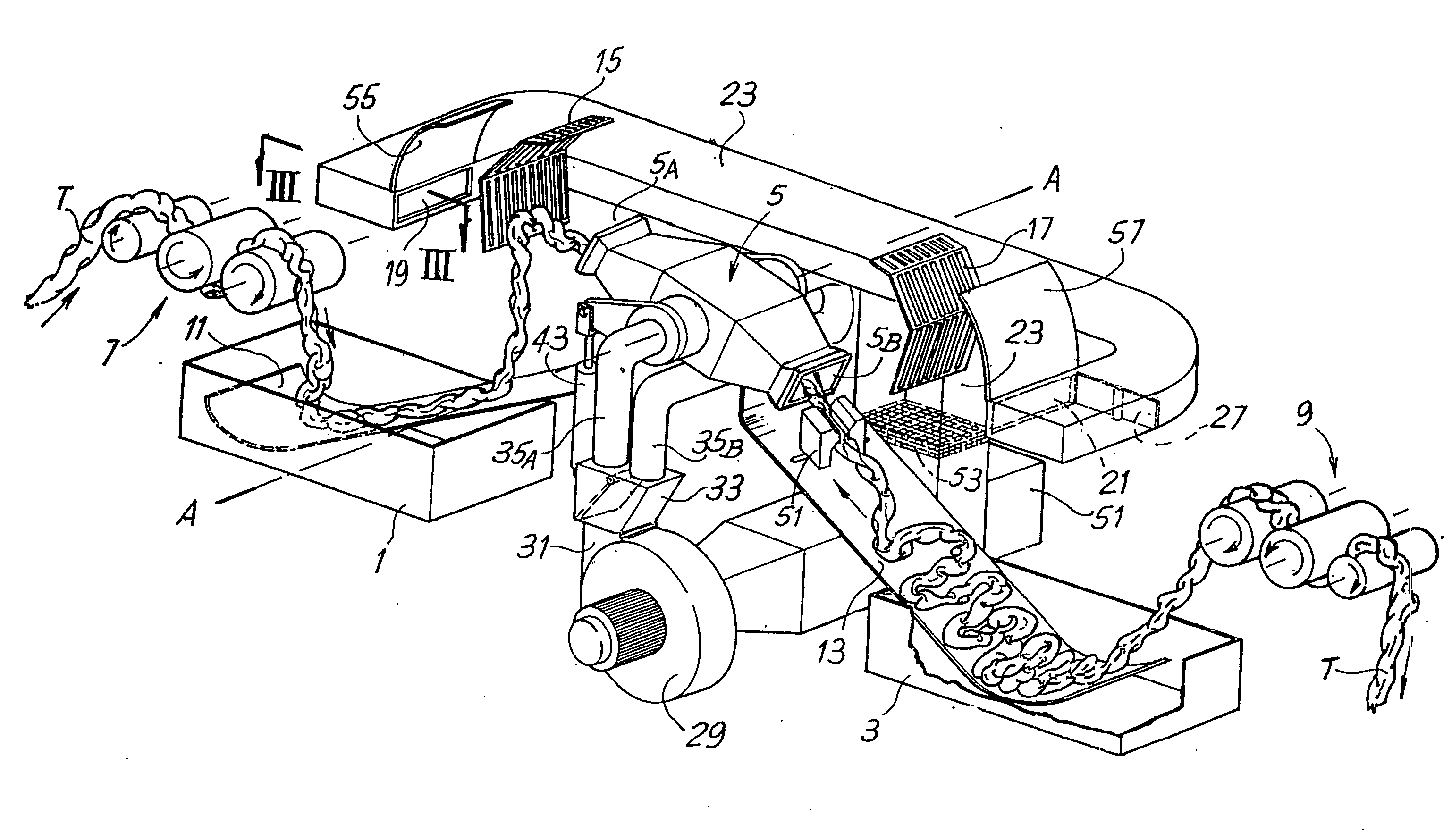
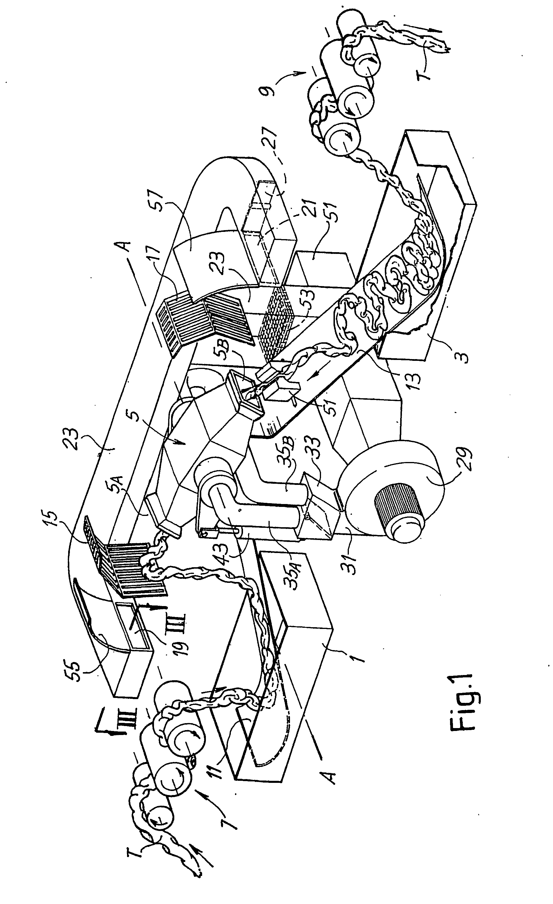
[0032]FIG. 1 shows the internal components of the machine in a perspective view, all the external containing walls and housing having been removed so as to provide an overall view of the inside of the machine itself.

[0033] In the example illustrated, the machine is designed for the treatment of fabric in rope form, as mentioned above, but may also be designed for the treatment of fabric in open width form.

[0034] The machine has inside it a first tank 1 and a second tank 3 which are positioned in series along a path for treatment of the fabric T and between which a transfer member denoted overall by 5 is arranged. The tank 1 has, associated with it, a conveying unit 7 for introduction of the fabric T, while the tank 3 has, associated with it, a second conveying unit 9 for extraction of the treated fabric from the machine. The two conveying units 7 and 9 have a plurality of cylinders, at least one of which is motorized so as to impart to the fabric T the necessary speed for insertio...


PUM


Abstract

The machine comprises in combination: means (7) for supplying the fabric (T); means (9) for extracting the fabric; at least one first tank (1) and one second tank (3) which are positioned in series and between which a pneumatic transfer member (5) for transferring the fabric alternately from the first tank to the second tank and vice versa is arranged. The pneumatic transfer member is pivotable so as to assume at least two positions depending on the direction of feeding of the fabric through said pivoting transfer member.

Description

TECHNICAL FIELD [0001] The present invention relates to a machine for the continuous treatment of a fabric. More particularly, the invention relates to a machine for the continuous treatment of a fabric both in open width form and preferably in rope form, with or without immersion in a bath. [0002] The invention also relates to a method for the continuous treatment of a fabric. STATE OF THE ART [0003] In the field of the processing and finishing of fabrics, machines which perform the treatment of lengths of fabric both with and without immersion in a bath are known, said machines conveying the fabric along a path where the fabric itself undergoes the mechanical action of one or more mechanical members and, if necessary, a chemical action by means of enzymes and / or a thermal action. [0004] This type of machine normally operates in a discontinuous cycle. This means that a section of fabric of finite length is introduced into the machine and closed, joining together the leading end and...

Claims


Application Information

Patent Timeline
IPC IPC(8): D06B3/28D06C19/00F26B13/10
CPCD06B3/28F26B13/103D06C19/00
Inventor MARCORA, LUIGICIABATTINI, ALBERTO
Owner CORAMTEX
Learn More