
Self-cleaning connector

a self-cleaning and connector technology, applied in the direction of coupling device connection, coupling contact member, coupling device engaging/disengaging, etc., can solve the problems of deteriorating the performance of the charger, the pins of the charger connector and the contacts of the mobile unit connector, and the exposure of the outside environmen

Inactive Publication Date: 2005-03-24
GOOGLE TECH HLDG LLC
View PDF8 Cites 49 Cited by
  • Summary
  • Abstract
  • Description
  • Claims
  • Application Information

AI Technical Summary

Benefits of technology

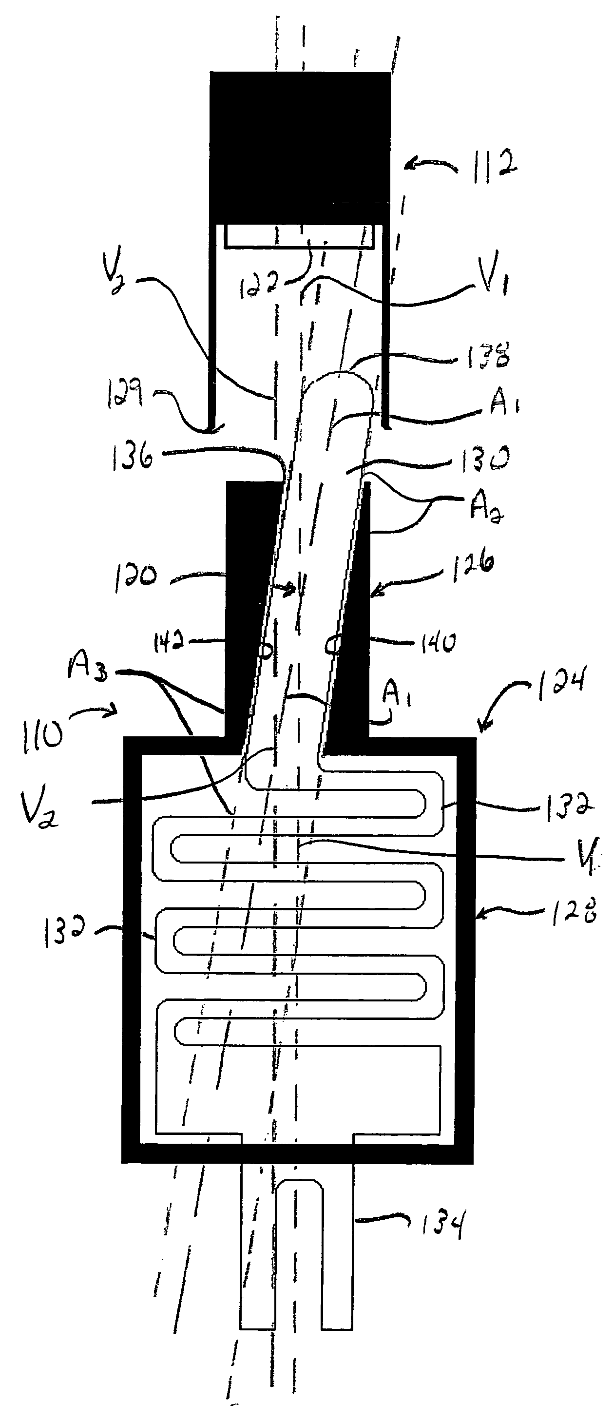
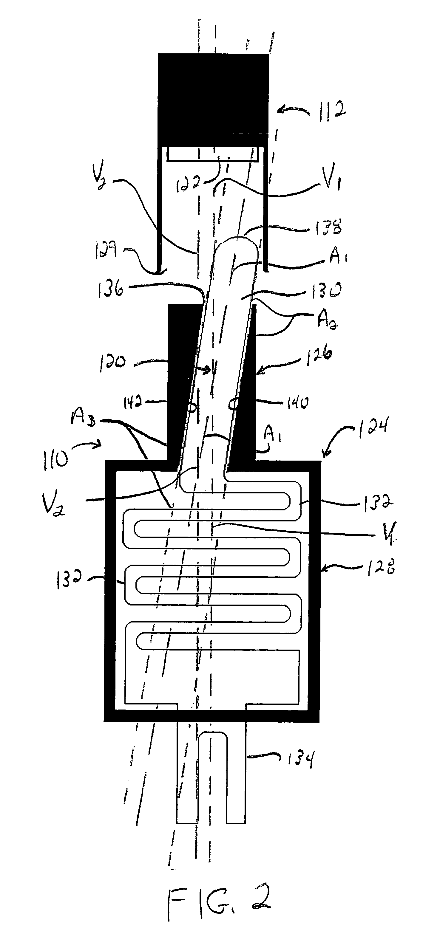
[0014] The first portion of the tunnel can further include a second inner surface opposed to the first inner surface in which the first inner surface and the second inner surface can be curved. The shape of the first inner surface and the second inner surface can substantially match the curved portion of the elongated portion. In addition, the second inner surface, in combination with the first inner surface, can force the pin in the first predetermined direction. In yet another arrangement, the first inner surface and the second inner surface can force the pin in a second predetermined direction in which the second predetermined direction can be a curved direction that is opposite that of the first predetermined direction. The second predetermined direction can cause the contact surface of the pin to slidably rotate against the contact of the corresponding connector.

Problems solved by technology

The pins of the charger connector and the contacts of the mobile unit connector, however, are typically exposed to the outside environment.
As such, dirt or other contaminants may collect on either the pins of the charger connector or the contacts of the cellular telephone connector.
If either of these components is contaminated in such a fashion, the electrical connection between them suffers, which can cause a degradation in the performance of the charger.
This drawback is not limited to chargers, however, as the pins and contacts in virtually any type of connector are susceptible to such contamination.

Method used


Image

  • Self-cleaning connector
  • Self-cleaning connector
  • Self-cleaning connector

Examples


Embodiment Construction

[0026] While the specification concludes with claims defining the features of the invention that are regarded as novel, it is believed that the invention will be better understood from a consideration of the following description in conjunction with the drawing figures, in which like reference numerals are carried forward.

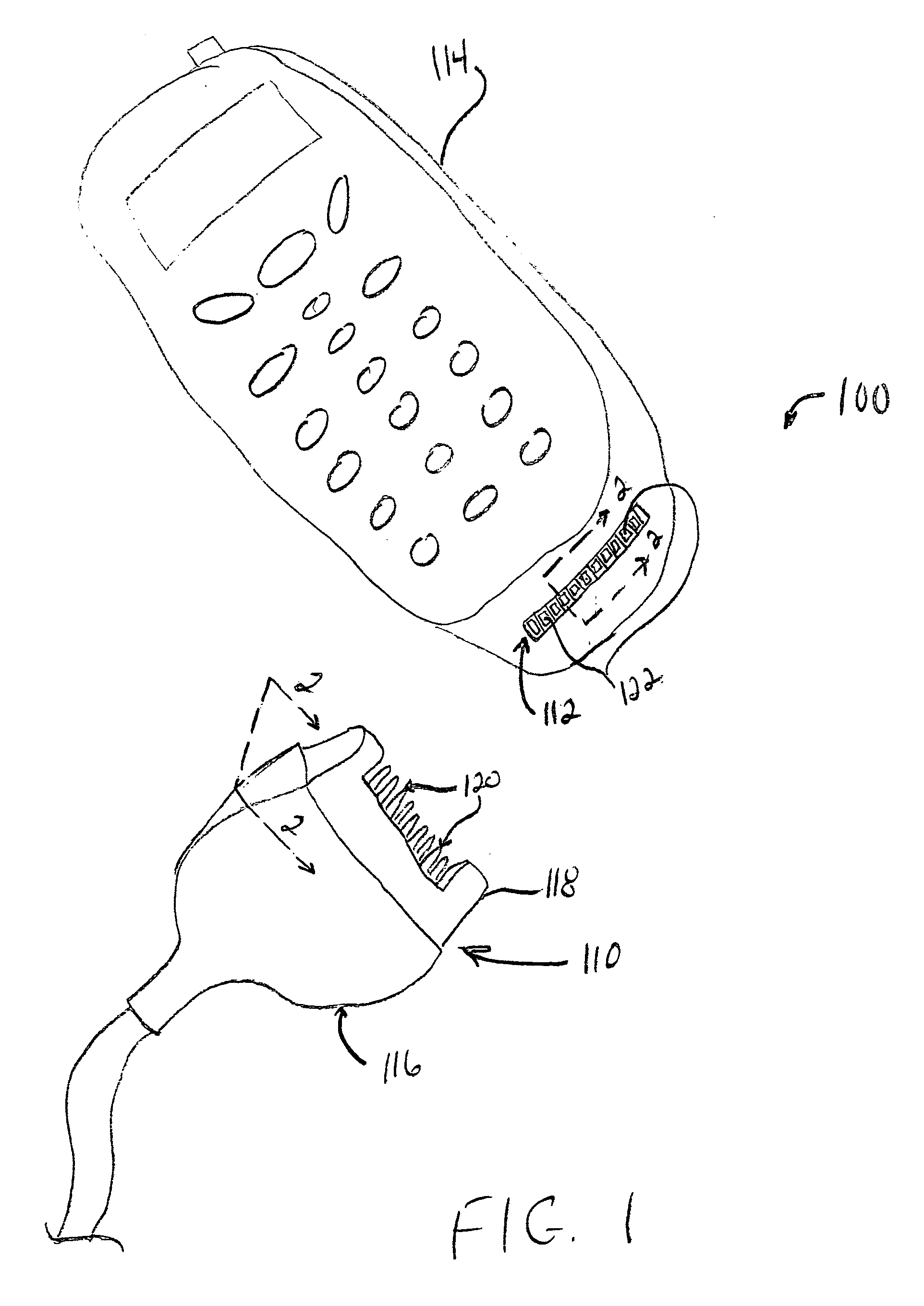
[0027] Referring to FIG. 1, a system 100 for cleaning contacts of corresponding connectors is shown. The system 100 can include a first connector 110 and a second connector 112 in which the first connector 110 and the second connector 112 can engage one another. As an example, the first connector 110 can be an accessory connector, such as a charger, and the second connector 112 can be part of an electronic device 114, such as a cellular telephone. It is understood, however, that the invention is not limited to this particular example, as the first connector 110 and the second connector 112 can be part of other suitable devices.

[0028] The first connector 110 can i...


PUM


Abstract

The invention concerns a connector (110). The connector includes at least one tunnel (124) having a first portion (126) and a second portion (128) and at least one pin (120). At least a portion of the pin is positioned within the tunnel. The first portion of the tunnel has a first inner surface (140). The first inner surface forces at least a portion of the pin in at least a first predetermined direction as the connector engages a corresponding connector (112). Contaminants are at least partially removed from at least one of the pin and the corresponding connector as the first inner surface forces the pin in the first predetermined direction.

Description

CROSS REFERENCE TO RELATED APPLICATIONS [0001] (Not Applicable) BACKGROUND [0002] 1. Technical Field [0003] This invention relates in general to connectors and more particularly, to electrical connectors that couple accessories to an electronic device. [0004] 2. Description of the Related Art [0005] Many electronic devices include electrical connectors that can be used to couple accessories to such devices. For example, most cellular telephones include a connector that can receive and engage a corresponding connector of a charger. The connector of the charger typically includes a set of pins and the connector of the mobile unit has a set of corresponding electrical contacts. When the charger connector is inserted in the connector of the mobile unit, the pins of the charger connector contact the contacts of the telephone connector, which can permit the charger to provide a charging current to the battery of the mobile unit. [0006] The pins of the charger connector and the contacts of...

Claims


Application Information

Patent Timeline
IPC IPC(8): H01R13/24H01R43/26
CPCH01R43/26H01R13/2428H01R33/965H01R13/22H01R13/20
Inventor SIMPSON, RUSSELL L.SMITH, SYBREN D.
Owner GOOGLE TECH HLDG LLC
Learn More