
Image reading apparatus

a technology of image reading and reading device, which is applied in the direction of electrographic process apparatus, instruments, optics, etc., can solve the problems of scale removal and inability to recycle, and achieve the effect of easy recycling or replacement of contact glass sheets and image reading units

Active Publication Date: 2005-03-24
KYOCERA DOCUMENT SOLUTIONS INC
View PDF13 Cites 2 Cited by
  • Summary
  • Abstract
  • Description
  • Claims
  • Application Information

AI Technical Summary

Benefits of technology

The present invention provides an image reading apparatus with a contact glass sheet that can be easily attached and detached from the frame body, and prevention of breakage and dust intrusion. The apparatus includes a frame body with an upper frame and a lower frame that can be detached from each other. Glass supports are provided to hold the contact glass sheet in place, and an adhesive member is used to secure the contact glass sheet to the upper frame. The invention also provides an improved method for positioning the contact glass sheet and ensuring its retention in place, even if the adhesive force decreases. Overall, the invention provides an image reading apparatus with improved ease of assembly, recycling efficiency, and prevention of contamination.

Problems solved by technology

Particularly, when the rear faces of the scale plates are adhered by means of double-sided adhesive tape all over to the contact glass sheet, if a flat-blade screwdriver-like tool is used to strip the scale plates from the contact glass sheet, it is not only difficult to remove the scale plates because the scale plates are thin, but also the contact glass sheet may be hurt or broken due to strong adhering force of the double-sided adhesive tape, resulting in that recycling becomes impossible.

Method used


Image

  • Image reading apparatus
  • Image reading apparatus
  • Image reading apparatus

Examples


Embodiment Construction

[0036] A preferred embodiment of the present invention will now be detailed with reference to the accompanying drawings. It is intended, however, that unless particularly specified, dimensions, materials, relative positions and so forth of the constituent parts in the embodiments shall be interpreted as illustrative only not as limitative of the scope of the present invention.

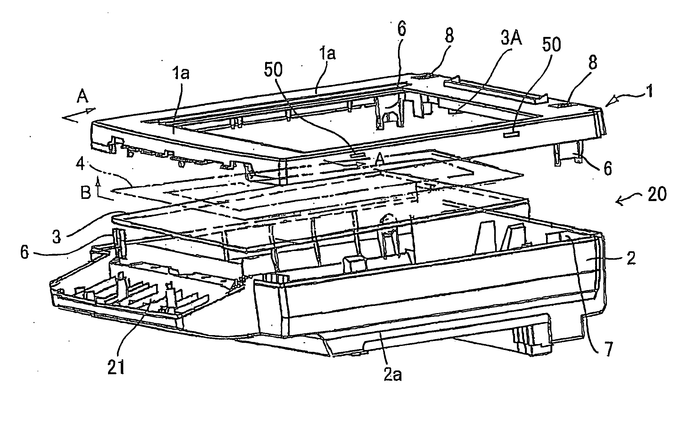
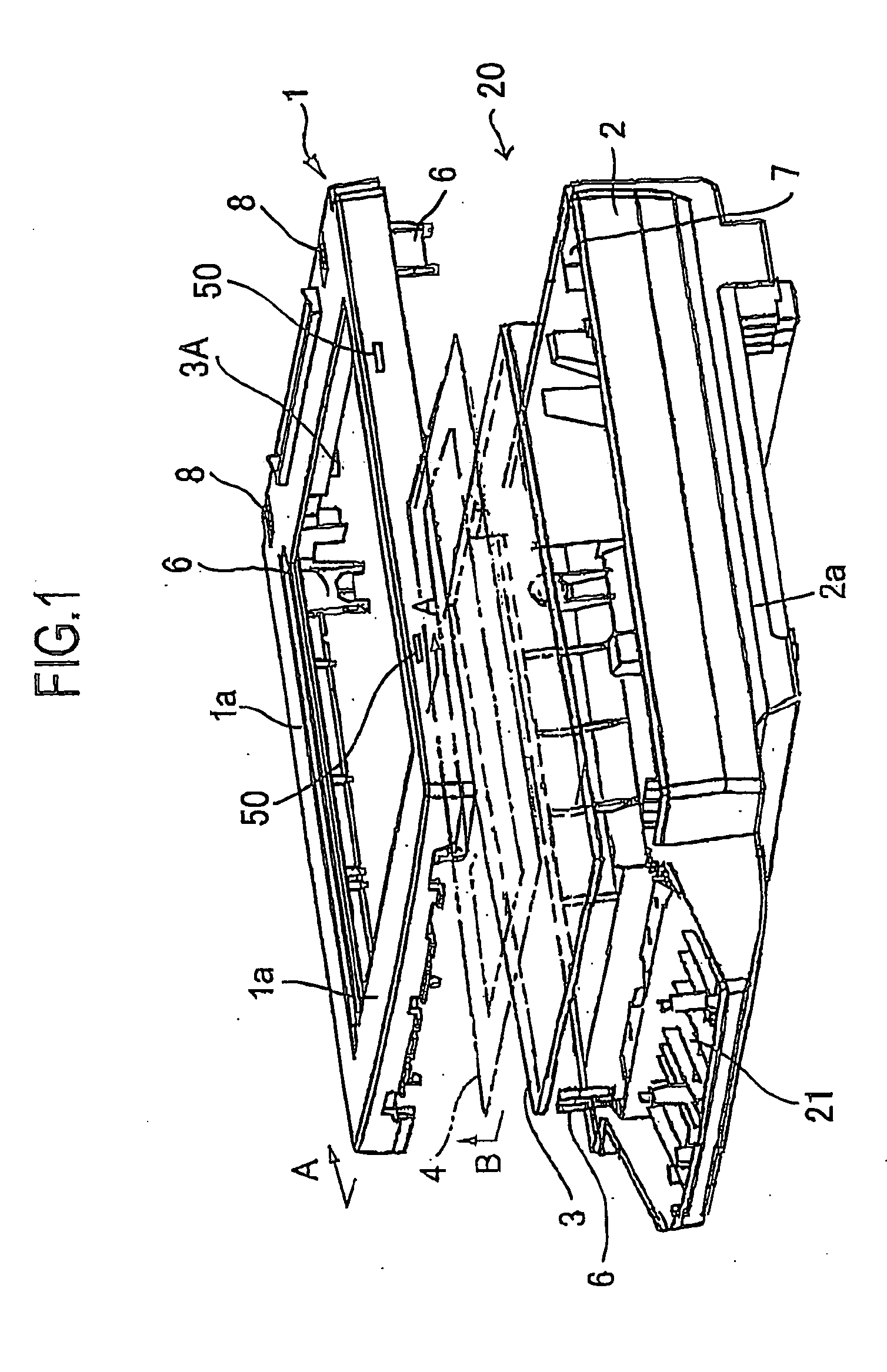
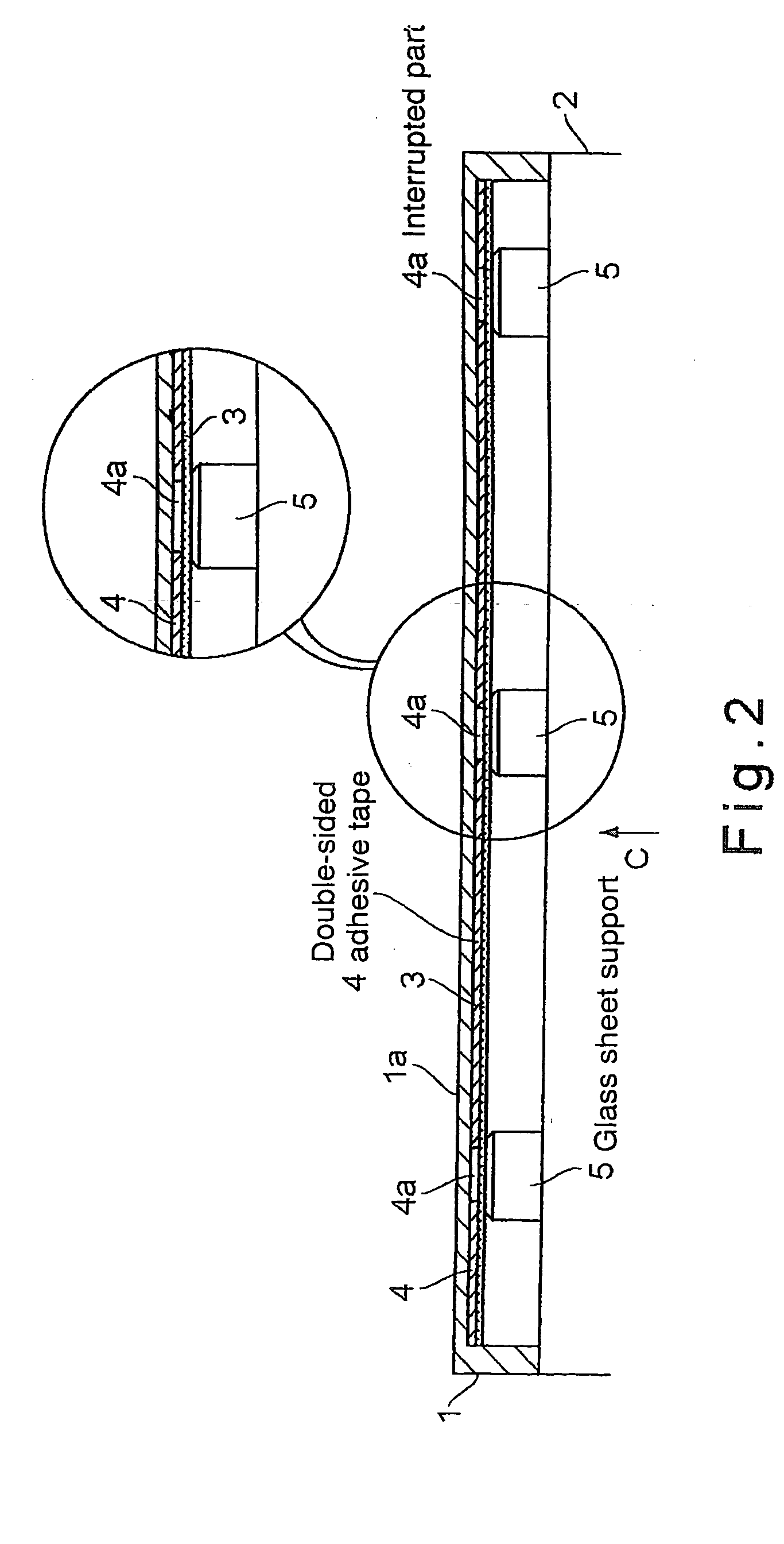
[0037]FIG. 1 is an exploded perspective view of the frame body of an embodiment of the image reading apparatus according to the present invention having only contact glass sheet in the case without a manuscript auto-feeding mechanism, FIG. 2 is a cross-sectional view along line A-A in FIG. 1, and FIG. 3 is a drawing for explaining the positioning relation of glass sheet supports to a double-sided adhesive tape. FIG. 4 is an exploded perspective view of the frame body of another embodiment of the image reading apparatus according to the present invention having a contact glass sheet and a slit glass sheet in wh...


PUM


Abstract

In order to provide an image reading apparatus of which a contact glass sheet can be replaced and recycled with ease without damaging the contact glass sheet when removing the same, and further intrusion of particles of dust into the apparatus when operating the apparatus can be prevented, an image reading apparatus having an image reading unit mounted to be able to be reciprocated in a frame body of the apparatus and a contact glass sheet is composed such that; the frame body comprises an upward-open lower frame in which the image reading unit is accommodated to be able to be reciprocated and an upper frame having an opening on the upper face thereof to be covered with the contact glass sheet, the upper and lower frames are assembled detachably by means of fitting portions provided to both frames, the contact glass sheet is attached to said upper frame by means of a strip-shaped adhesive member glued onto the undersurface of the upper frame along the brim part of the opening to be covered with the contact glass sheet, the strip-shaped adhesive member is glued onto the undersurface of the upper frame so that the strip is not continuous but partially interrupted to provide interrupted parts, and the glass sheet supports protruding from the lower frame are positioned to support the contact glass sheet at the position corresponding to the interrupted parts of the strip-shaped adhesive member.

Description

BACKGROUND OF THE INVENTION [0001] 1. Field of the invention [0002] The present invention is related to an image reading apparatus in which an image reading unit integrating a CCD (Charge Coupled Device) and an optical system comprising a reflection mirror, a condensing lens, etc. is installed to reciprocate in a flame body, specifically an image reading apparatus provided with a contact glass sheet on the upper face of the flame body and a sheet of manuscript to be read is placed on the contact glass sheet when reading. [0003] 2. Description of the Related Art [0004] Recently, recycling of constituent parts of industrial machines is proceeding in all industrial circles. As to copying machines and scanner, etc., frames, etc. are generally made of plastic material, and the optical system integrated in the image reading unit is fixed by means of screws and the like for allowing it to be adjusted. Therefore, said optical system is easily detachable for recycling or replacement. The con...

Claims


Application Information

Patent Timeline
Patent Type & Authority Applications(United States)
IPC IPC(8): H04N1/04H04N1/10H04N1/192
CPCH04N1/1017H04N2201/0446H04N2201/0422H04N1/192
Inventor TSUJIMOTO, KOICHIROHOZONO, TOMOHIDEKOTERA, SHINICHI
Owner KYOCERA DOCUMENT SOLUTIONS INC
Learn More