
High-linearity switched-resistor network for programmability

a switched resistor and high-linearity technology, applied in the direction of resistors, adjustable resistors, electrical appliances, etc., can solve the problems of non-linear equivalent resistance and problems that aris

Inactive Publication Date: 2005-03-24
AVAGO TECH WIRELESS IP SINGAPORE PTE
View PDF11 Cites 12 Cited by
  • Summary
  • Abstract
  • Description
  • Claims
  • Application Information

AI Technical Summary

Problems solved by technology

Problems can arise when transistors (e.g., MOSFETS) are used for the switches because they exhibit non-linear behavior.
This can result in a non-linear equivalent resistance.

Method used


Image

  • High-linearity switched-resistor network for programmability
  • High-linearity switched-resistor network for programmability
  • High-linearity switched-resistor network for programmability

Examples


Embodiment Construction

[0016] Overview

[0017] While specific configurations and arrangements are discussed, it should be understood that this is done for illustrative purposes only. A person skilled in the pertinent art will recognize that other configurations and arrangements can be used without departing from the spirit and scope of the present invention. It will be apparent to a person skilled in the pertinent art that this invention can also be employed in a variety of other applications.

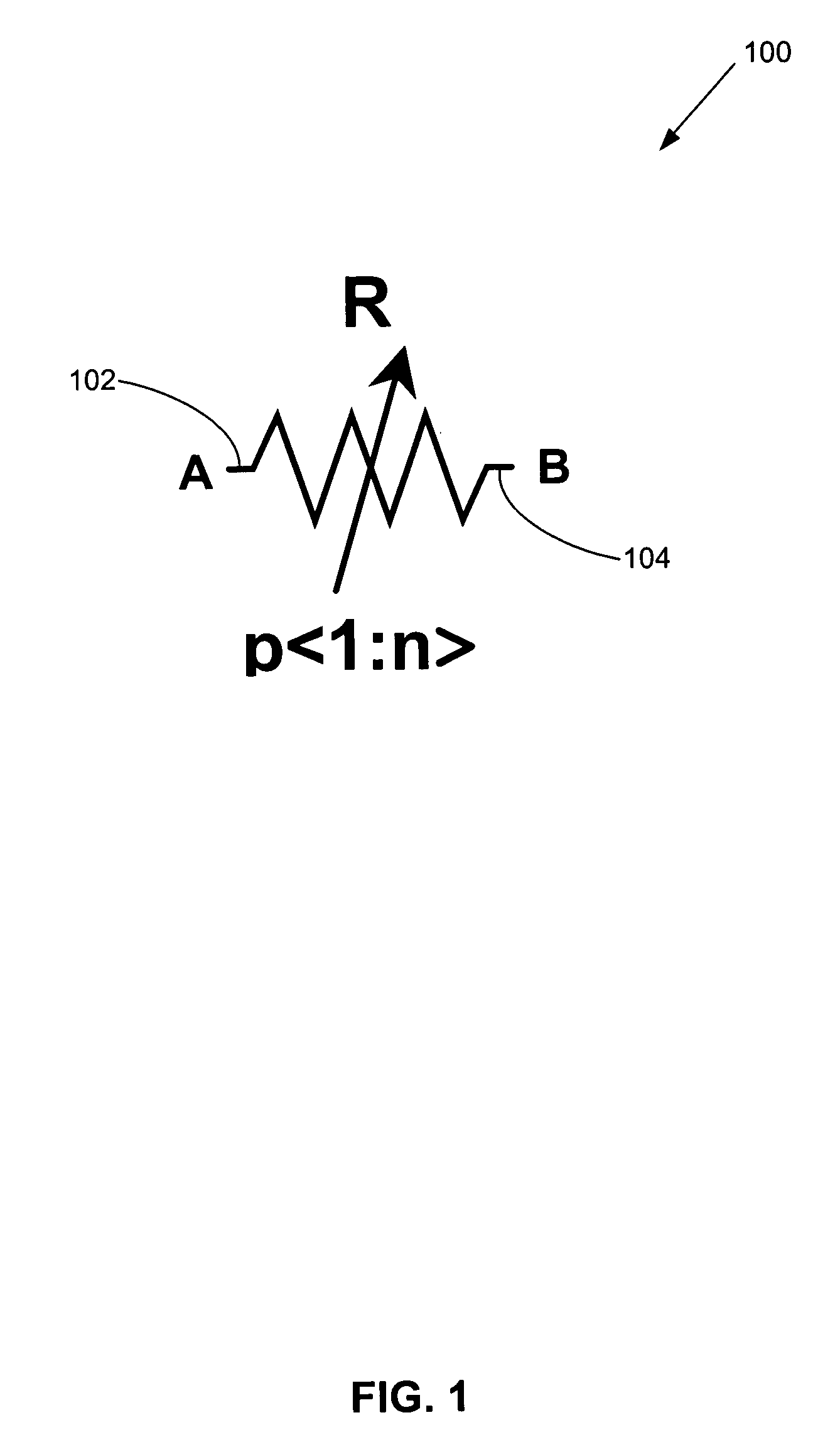
[0018]FIG. 1 shows a programmable resistor 100 coupled between a node A and a node B.

[0019] Programmable Resistive Devices with Series Connected Resistors

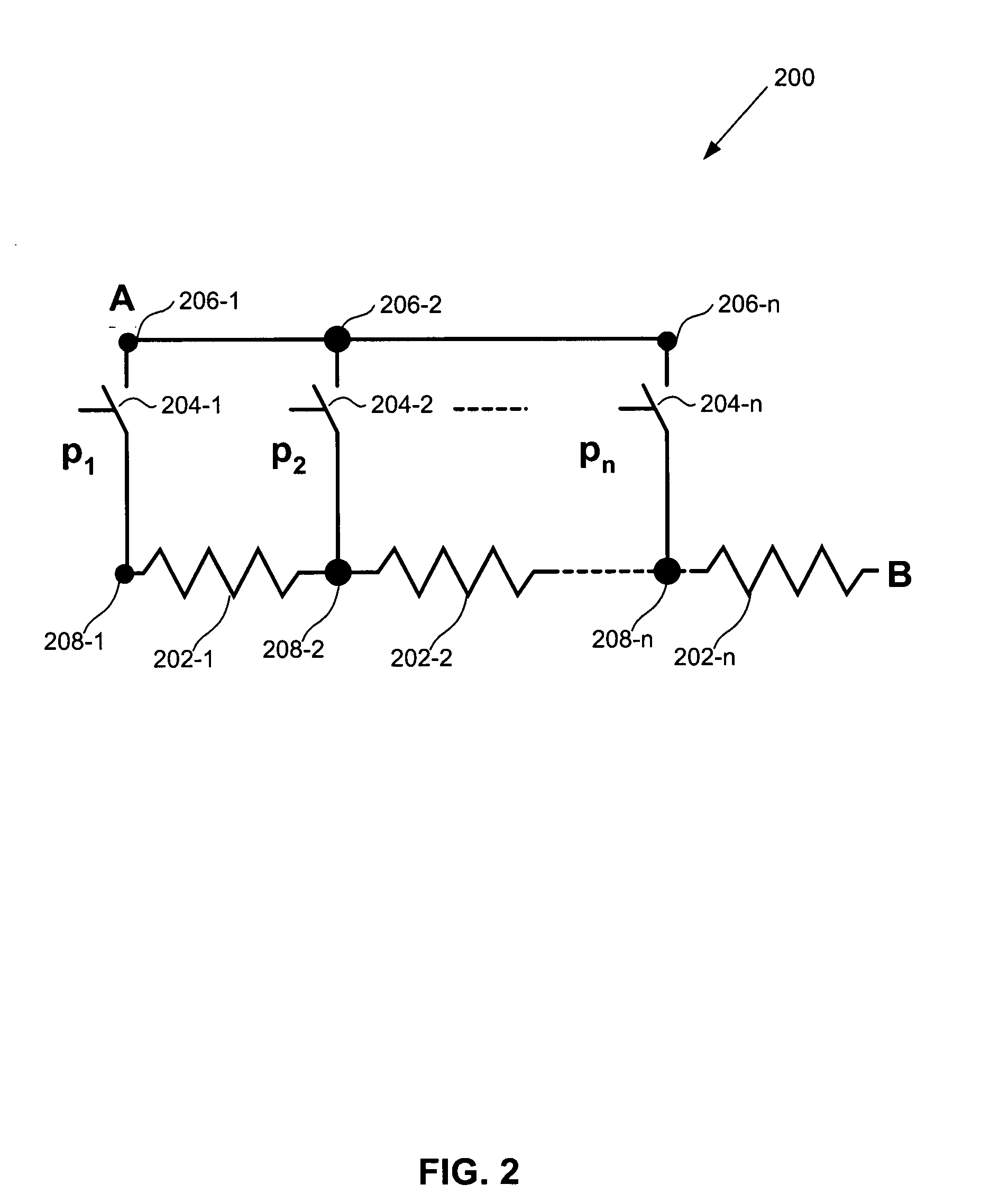
[0020]FIGS. 2-3 show two configurations for programmable resistive devices 200 and 300 having series connected resistors coupled between nodes A and B.

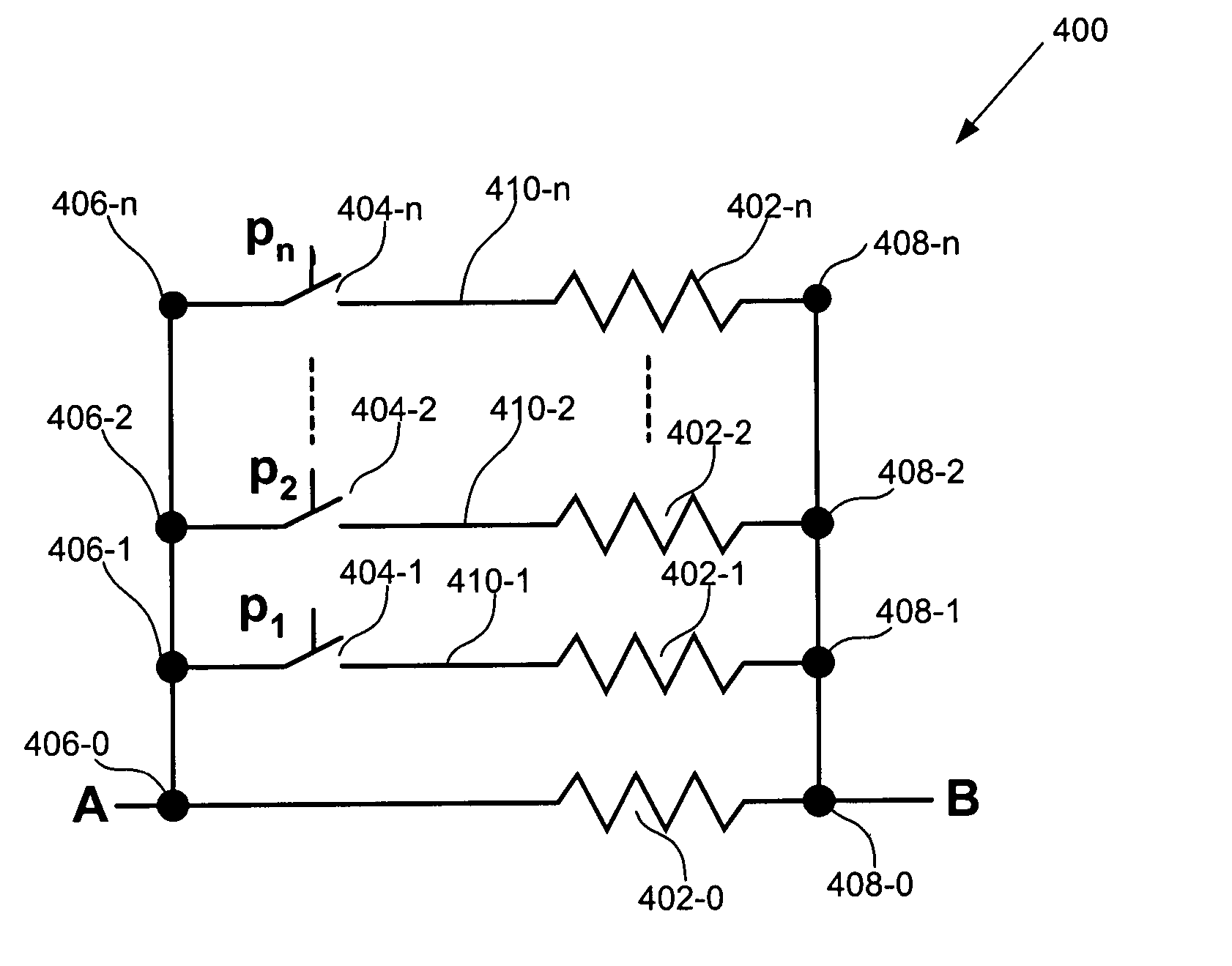
[0021] With reference to FIG. 2, programmable resistive device 200 includes series resistors 202-1 to 202-n (n is an integer greater than 1) and switches 204-1 to 204-n. Switches 204 are coupled between nodes 206-1...


PUM


Abstract

A system (e.g., a programmable resistive device) including switches and resistors. Respective ones of each of the switches is connected in series with respective ones of each of the resistors to form switch-resistor branches. The switch-resistor branches are connected in parallel between first and second nodes. Respective ones of the switches receive control signals to turn them ON, which forms an equivalent resistor having an equivalent resistance. A resistance of the switch is substantially insignificant compared to a resistance of the resistor in each of the switch-resistor branches making the equivalent resistance substantially linear.

Description

BACKGROUND OF THE INVENTION [0001] 1. Field of the Invention [0002] The present invention is related to programmable switched-resistor networks. [0003] 2. Background Art [0004] Many chips have devices that require a different resistance during different operations of the chip. For example, programmable gain amplifiers require different resistance in feedback paths from their output to their inverting and non-inverting input nodes during different operations. [0005] Typically, programmable resistive devices are used to most effectively allow for variable resistance in these devices. Programmable resistive devices usually have an array of resistors coupled in series between first and second nodes. A switch is associated with each resistor. A particular switch or number of switches that are ON control how many of the resistors are in a signal flow path (e.g., a current path) for a particular operation. The total number of resistor in series forms an equivalent resistance equaling a des...

Claims


Application Information

Patent Timeline
Patent Type & Authority Applications(United States)
IPC IPC(8): H03M11/24
CPCH03M11/24
Inventor WANG, HONGWEI
Owner AVAGO TECH WIRELESS IP SINGAPORE PTE
Learn More