
High density fiber optic distribution frame

a high-density fiber optic and distribution frame technology, applied in the direction of optics, fibre mechanical structures, instruments, etc., can solve the problems of not providing the combination of features necessary to address all of the deficiencies, the known distribution frame is typically not compatible with existing fiber optic hardware, and the known high-density fiber optic distribution frame has certain deficiencies

Inactive Publication Date: 2005-03-17
CORNING OPTICAL COMM LLC
View PDF22 Cites 74 Cited by
  • Summary
  • Abstract
  • Description
  • Claims
  • Application Information

AI Technical Summary

Benefits of technology

The solution enables seamless integration with legacy systems, maintains the integrity of optical signals by controlling bend radius, and optimizes frame dimensions by efficiently managing jumper lengths and storage, addressing the limitations of existing frames.

Problems solved by technology

Each of the known high density fiber optic distribution frames, however, has certain deficiencies and none provides a combination of features necessary to address all of the deficiencies.
For example, the known distribution frames are typically not compatible with existing fiber optic hardware, commonly referred to as “legacy” hardware.
In particular, the existing distribution frames are not compatible with legacy connector housings, such as LGX® connector housings available from American Telephone and Telegraph Corporation (AT&T Corp.) of New York, N.Y. or LDC™ connector housings available from Coming Cable Systems LLC of Hickory, N.C.
In addition, the known distribution frames do not include a frame assembly that adequately controls the bend radius of the optical fiber as the jumpers transition on the frame between connector modules.
Further, the known distribution frames do not include an Interbay Fiber Manager (IFM) that can be readily configured with the distribution frame for convenient storage and routing of optical fiber, while maintaining the minimum bend radius of the optical fiber.
The slack lengths of the jumpers tend to accumulate, or “pile-up,” adjacent the base of the distribution frame, thereby unnecessarily increasing the lateral and depth dimensions of the frame.

Method used


Image

  • High density fiber optic distribution frame
  • High density fiber optic distribution frame
  • High density fiber optic distribution frame

Examples


Embodiment Construction

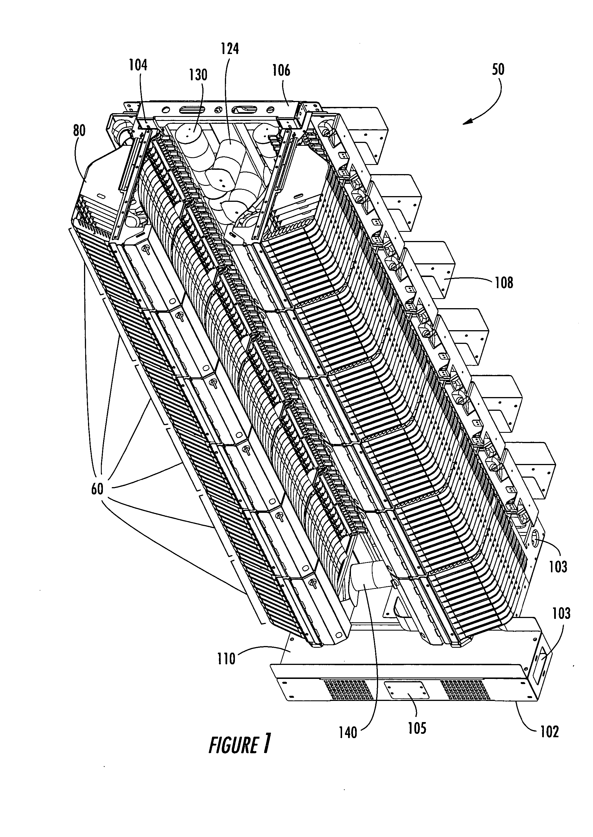
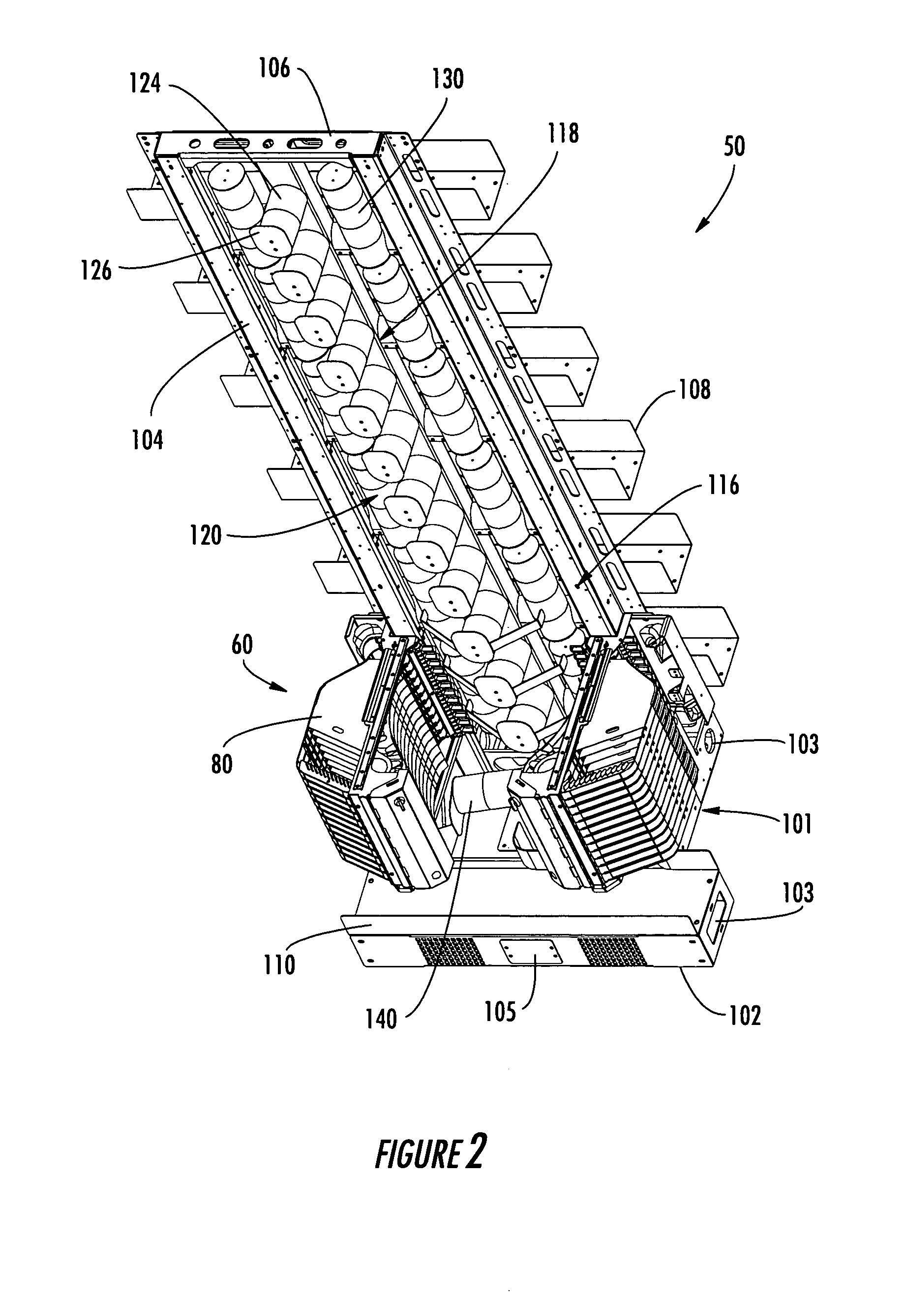
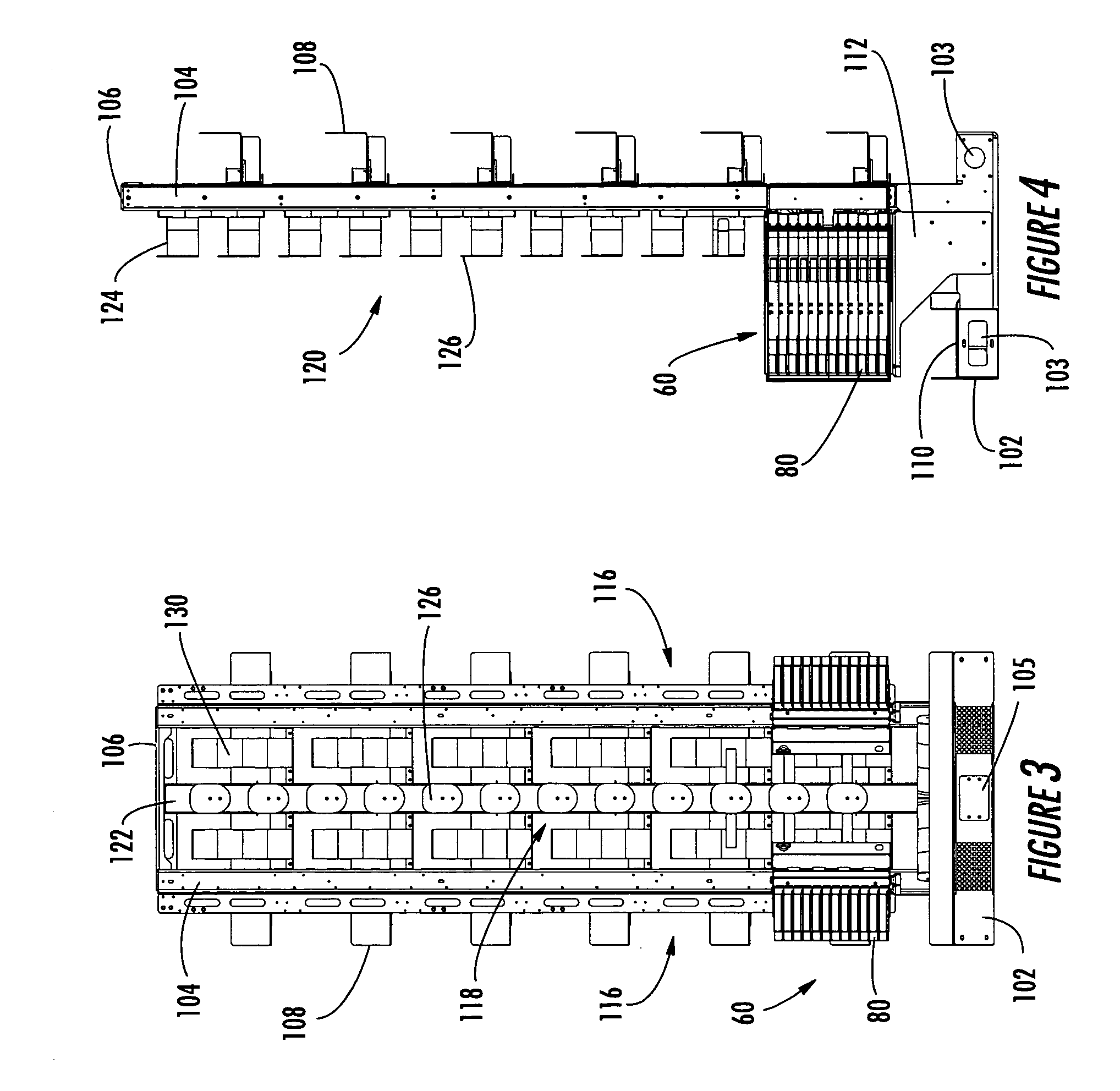
[0052] The invention is described in greater detail hereinafter with reference to the accompanying drawings, in which various exemplary embodiments of the invention are shown. The invention may, however, be embodied in many different forms, and therefore, should not be construed as being limited to the embodiments described and shown herein. Exemplary embodiments are set forth herein so that this description will be thorough and complete and will fully convey the best mode and intended scope of the claimed invention, while enabling those skilled in the art to make and practice the invention without undue experimentation. Like reference numerals are utilized throughout the drawing figures to identify the same or similar parts in the embodiments shown and described. However, no particular significance should be afforded the reference numbers. Likewise, no particular significance should be afforded to the relative size or scale of the components depicted in the drawing figures, unless ...


PUM


Abstract

A high density fiber optic distribution frame includes a frame assembly, one or more left-hand connector module housings mounted on the frame assembly, one or more right-hand connector module housings mounted on the frame assembly and an Interbay Storage Unit (IBU) positioned on the frame assembly medially between the left-hand connector module housings and the right-hand connector module housings. Each connector module housing includes one or more connector modules having one or more adapters for interconnecting optical fibers between connector modules on the distribution frame or on an adjacent distribution frame in a communications network. The distribution frame is compatible with existing fiber optic connector housings, maintains the minimum bend radius of the optical fibers transitioned on the frame between connector modules, and reduces the length of a single length jumper employed on the frame. An alternative embodiment includes an Interbay Fiber Manager (IFM) for routing and storing additional jumpers.

Description

FIELD OF THE INVENTION [0001] The invention relates to distribution frames for use in a communications network. More, particularly, the invention is an improved high density fiber optic distribution frame for interconnecting optical fibers in a communications network. BACKGROUND OF THE INVENTION [0002] Distribution frames are widely utilized, for example in a building communications network, to interconnect optical fibers. Such distribution frames are sometimes also referred to as “termination” or “cross-connect” frames because they include connector modules having adapters and jumper cables or “jumpers” that extend between two connector modules to interconnect optical fibers terminated at adapters within the connector modules. The increasing demand for communications services, particularly within office buildings and technology centers, requires that new distribution frames be able to interconnect a greater number of optical fibers. This requirement is commonly referred to as “term...

Claims


Application Information

Patent Timeline
Patent Type & Authority Applications(United States)
IPC IPC(8): G02B6/44
CPCG02B6/4452G02B6/44524G02B6/44528
Inventor DAGLEY, MARK R.NORED, LEE W.WORKS, ANTWAN J.RODOLFO, SAUL L.SEGELHORST, JON P.NGUYEN, TUY T.GIRAUD, WILLIAM J.M.DAVIDSON, DONALD G.
Owner CORNING OPTICAL COMM LLC
Learn More