
Method and system for measuring the wavelength dispersion and nonlinear coefficient of an optical fiber, method of manufacturing optical fibers, method of measuring wavelength-dispersion distribution, method of compensating for measurement errors, and method of specifying conditions of measurement

a technology of which is applied in the field of method and system for measuring wavelength dispersion and nonlinear coefficient of optical fiber, manufacturing optical fiber, and measuring wavelength-dispersion distribution, which can solve problems such as adversely affecting transmission quality, affecting the performance of optical transmission lines, and affecting the transmission quality of optical transmission lines. , to achieve the effect of reducing the number of optical transmission lines, and improving the quality

Active Publication Date: 2005-03-17
FURUKAWA ELECTRIC CO LTD
View PDF1 Cites 16 Cited by
  • Summary
  • Abstract
  • Description
  • Claims
  • Application Information

AI Technical Summary

Benefits of technology

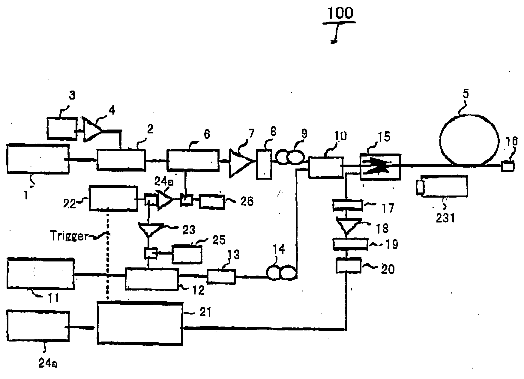
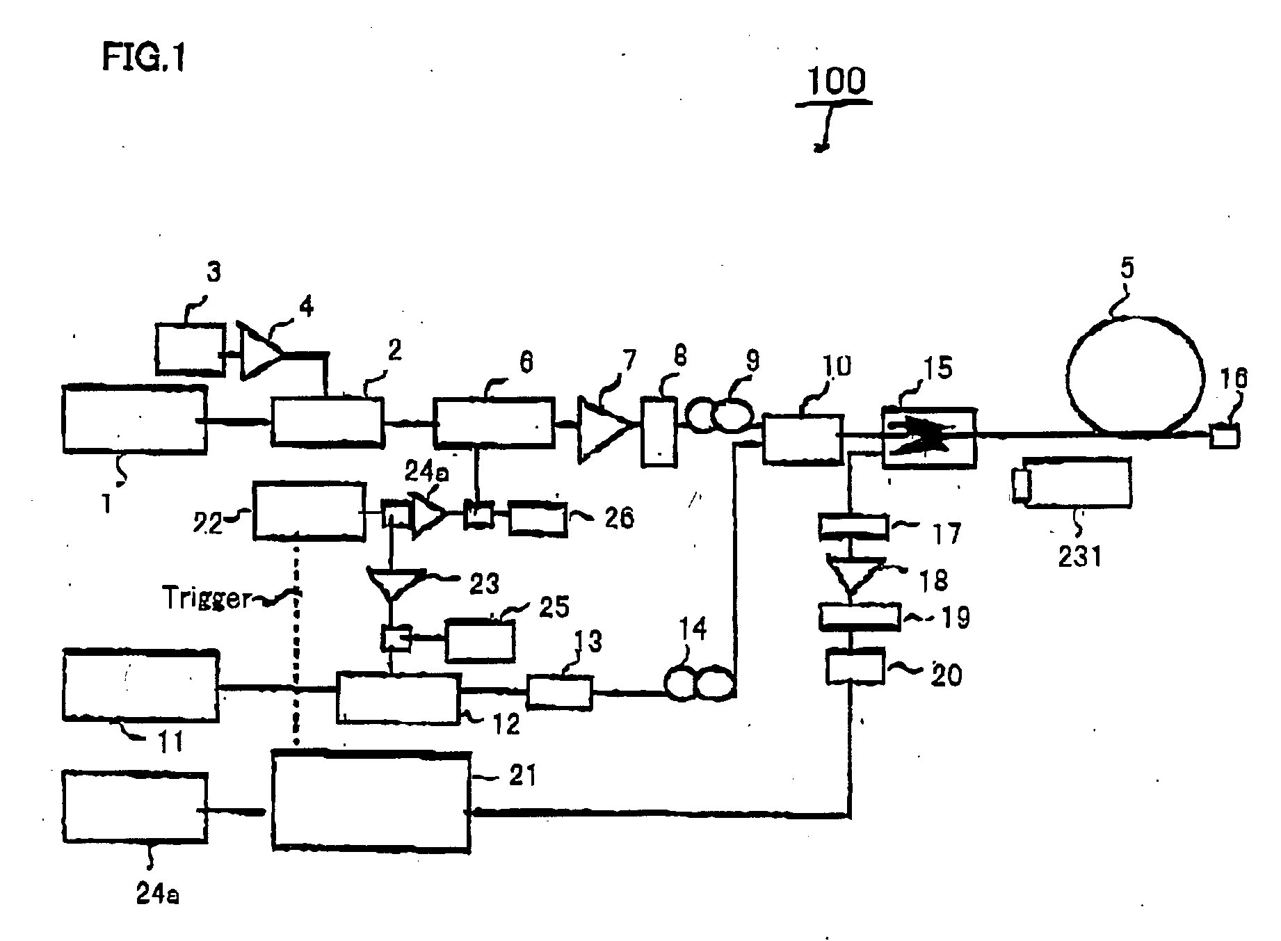
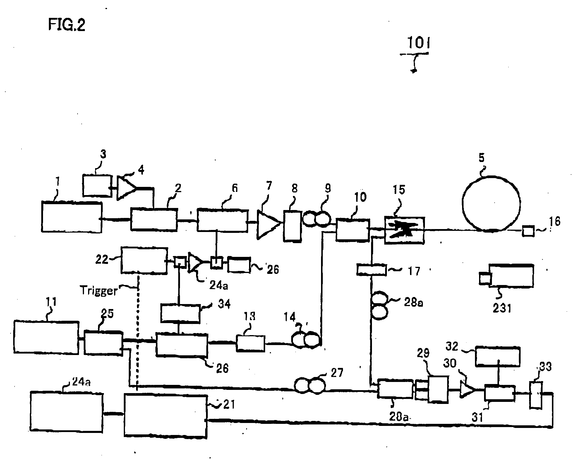
The present invention has been made in order to solve the above-described problems. Accordingly, the primary object of the invention is to make it possible to measure the wavelength-dispersion distribution and nonlinear-coefficient distribution in the longitudinal direction of an optical fiber to be measured, by making use of nonlinear optical effects that occur in the optical fiber.

Problems solved by technology

Also, in optical repeatered systems employing optical amplifiers, nonlinear optical effects become problems as optical signals of high power pass through optical fibers.
Nonlinear effects that arise within optical fibers are self-phase modulation (SPM), cross-phase modulation (CPM), four-wave mixing (FWM), etc., which adversely affect transmission quality.
On the other hand, the suppression of FWM against wavelength dispersion in optical transmission lines conflicts with the conditions of waveform distortion due to wavelength dispersion.
However, the wavelength dispersion of an optical fiber being actually used is not always uniform at a certain wavelength in the fiber longitudinal direction.
The prime cause is errors in manufacturing optical fibers and cables, etc.
Because it is difficult to calculate the strict solutions of Eqs.
However, at present, there is no means of measuring variations in the nonlinear coefficient in the longitudinal direction of an optical fiber.
Therefore, there is no investigation of how variations in the nonlinear coefficient in the longitudinal direction of an optical fiber affect the design of optical transmission lines and other optical transmission analyses.
In addition, a change in the diameter of glass when being drawing into fiber form is considered to be the main cause of variations in the wavelength dispersion in the fiber longitudinal direction produced when manufacturing optical fibers.
However, since there is an error in the accuracy of finishing in the fiber material or a measurement error in the preform analyzer, not a few variations will arise in the fiber longitudinal direction.

Method used


Image

  • Method and system for measuring the wavelength dispersion and nonlinear coefficient of an optical fiber, method of manufacturing optical fibers, method of measuring wavelength-dispersion distribution, method of compensating for measurement errors, and method of specifying conditions of measurement
  • Method and system for measuring the wavelength dispersion and nonlinear coefficient of an optical fiber, method of manufacturing optical fibers, method of measuring wavelength-dispersion distribution, method of compensating for measurement errors, and method of specifying conditions of measurement
  • Method and system for measuring the wavelength dispersion and nonlinear coefficient of an optical fiber, method of manufacturing optical fibers, method of measuring wavelength-dispersion distribution, method of compensating for measurement errors, and method of specifying conditions of measurement

Examples


case c

The power of pump light at points in the fiber longitudinal direction is calculated from the power of input pump light and fiber loss coefficient d. And by employing these values, ga and gb are calculated. In the above-described two cases, (C1) When Δβ<0 (anomalous dispersion) and Pp0>−Δβ / 4γ, ga=12⁡[-Δ⁢ ⁢β⁡(Δ⁢ ⁢β+4⁢γ⁢ ⁢Pp⁢exp⁡(-α⁢ ⁢z))]12(24) (C2) When Δβ<0 (anomalous dispersion) and Pp0>−Δβ / 4 γ, or when Δβ≧0 (normal dispersion), gb=12⁡[Δ⁢ ⁢β⁡(Δ⁢ ⁢β+4⁢γ⁢ ⁢Pp⁢exp⁡(-α⁢ ⁢z))]12(25)

Case D:

The power Pp(z) of pump light at points in the fiber longitudinal direction is actually measured by measuring the back-scattered light of pump light. And by employing these values, ga and gb are calculated. As with the case C, (D1) When Δβ<0 (anomalous dispersion) and Pp0>−Δβ / 4γ, ga=12⁡[-Δ⁢ ⁢β⁡(Δ⁢ ⁢β+4⁢γ⁢ ⁢Pp⁢exp( ⁢z))]12(26) (D2) When Δβ<0 (anomalous dispersion) and Pp0>−Δβ / 4γ, or when Δβ≧0 (normal dispersion), gb=12⁡[Δ⁢ ⁢β⁡(Δ⁢ ⁢β+4⁢γ⁢ ⁢Pp( ⁢z))]12(27)

In the case of opti...


PUM


Abstract

A method of simultaneously specifying the wavelength dispersion and nonlinear coefficient of an optical fiber. Pulsed probe light and pulsed pump light are first caused to enter an optical fiber to be measured. Then, the power oscillation of the back-scattered light of the probe light or idler light generated within the optical fiber is measured. Next, the instantaneous frequency of the measured power oscillation is obtained, and the dependency of the instantaneous frequency relative to the power oscillation of the pump light in a longitudinal direction of the optical fiber is obtained. Thereafter, a rate of change in the longitudinal direction between phase-mismatching conditions and nonlinear coefficient of the optical fiber is obtained from the dependency of the instantaneous frequency. And based on the rate of change, the longitudinal wavelength-dispersion distribution and longitudinal nonlinear-coefficient distribution of thee optical fiber are simultaneously specified.

Description

BACKGROUND OF THE INVENTION 1. Field of the Invention The present invention relates to a method and system for measuring the wavelength dispersion and nonlinear coefficient of an optical fiber, a method of manufacturing optical fibers, a method of measuring wavelength-dispersion distribution, a method of compensating for measurement errors, and a method specifying the measuring conditions. 2. Description of the Related Art With the liberalization of the field of information communication and the development of information society, there is a tendency for the amount of information to increase exponentially. By practical use of erbium-doped fiber amplifiers (EDFAs) and Raman fiber amplifiers that directly amplify light, optical signals of extremely high power can be obtained in the band of wavelength 1.55 μm. This can make up for the transmission losses in optical fibers and make repeaterless transmission possible over thousands of kilometers. By employing such a light amplificati...

Claims


Application Information

Patent Timeline
IPC IPC(8): G01M11/00G02B6/02H04B10/08H04B10/18
CPCG01M11/31G01M11/3172G01M11/39G01M11/319G01M11/3181
Inventor TADAKUMA, MASATERUMIMURA, YUSAKANO, MISAOASO, OSAMUNAKAJIMA, TAKESHITAKAHASHI, KATSUTOSHI
Owner FURUKAWA ELECTRIC CO LTD
Learn More